

Contents
- Why Geometry Decides Accuracy
- Blanking Distance: Sizing the Dead Zone
- Five-Step Mounting Procedure
- Beam Angle and Clearance Math
- Avoiding False Echoes from Internals and Foam
- Outdoor Installation: Sun, Wind, Rain
- Commissioning: 6 Calibration Steps
- Common Installation Mistakes
- Ultrasonic Level Sensors from Sino-Inst
- FAQ


Why Geometry Decides Accuracy
An ultrasonic level transmitter sends a pulse, listens for the echo, multiplies travel time by the speed of sound, and divides by two. The math is simple. What goes wrong in the field is almost always geometry: the sensor mounted too close to the maximum liquid level, too close to a tank wall, aimed at an agitator, or staring into a foam blanket. Get the install right and accuracy lands inside ±0.25% of range; get it wrong and the reading drops out or sticks at one value. For comparison with other tank gauging methods, see our overview of ultrasonic tank level sensors.
This guide walks through the geometry rules — dead zone, beam angle, clearance, false echoes — and finishes with a six-step calibration procedure that works for any 40, 75, or 120 kHz transducer. For a deeper background on how the sensor itself works, see our explainer on ultrasonic level transmitters.
Blanking Distance: Sizing the Dead Zone
The blanking distance (also called the dead zone or near zone) is the volume directly in front of the transducer where no measurement is possible. The transducer needs time to stop physically vibrating after each transmit pulse before it can listen for the returning echo. Read inside the blanking distance and you get the transducer’s own ring-down, not the liquid surface.
| Frequency | Typical range | Typical blanking | Beam angle |
|---|---|---|---|
| 40 kHz | 0.3 – 8 m | 0.3 m (12 in) | 10°–12° |
| 75 kHz | 0.25 – 5 m | 0.25 m (10 in) | 8°–10° |
| 120 kHz | 0.2 – 3 m | 0.15 m (6 in) | 6°–8° |
| 200 kHz | 0.1 – 1.5 m | 0.1 m (4 in) | 5°–6° |
Sizing rule: the maximum liquid level must sit at least one blanking distance below the transducer face. For a 40 kHz sensor with 300 mm blanking installed on a 6 m tank, the highest accepted level is 6.0 − 0.3 = 5.7 m. Operators usually add another 100–200 mm of safety margin because waves and turbulence push the apparent surface upward.
Five-Step Mounting Procedure
- Confirm the mounting flange location. The sensor face must be at least one blanking distance above the highest expected level. For roof-mounted installs on closed tanks, use the NPT or flange already specified for the model. Hand-tighten threaded sensors — overtightening cracks the housing.
- Verify perpendicularity. The transducer face must aim straight down within ±2°. A 1 m offset at 5° tilt loses 70% of return signal strength. Use a small bubble level on the threaded boss before final tightening.
- Check clearance to the nearest wall or fitting. Half-beam-angle clearance is the minimum (see calculation in next section). On a 6 m tank with a 40 kHz sensor, that means staying 0.6 m from the wall.
- Cable the transducer with shielded twisted pair. Run separately from variable-frequency-drive cables to avoid EMI pickup. Ground the shield at the controller end only.
- Energize and check the empty echo. With the tank empty, the displayed level should read maximum range. If the screen shows “lost echo,” the sensor is either aimed at a fitting or above its rated range.

Beam Angle and Clearance Math
The ultrasonic beam spreads as a cone. The half-angle θ/2 gives the minimum clearance to any wall, ladder, or pipe inside the tank. The footprint radius at a sensing distance d is:
r = d × tan(θ/2)
For a 75 kHz sensor with a 9° total beam (4.5° half angle) at 4 m range:
r = 4 × tan(4.5°) = 4 × 0.0787 = 0.315 m
So nothing — ladder, baffle, internal nozzle, agitator shaft — can be within 315 mm of the beam axis at 4 m below the sensor. Anything inside that cone returns an echo that the transmitter cannot distinguish from the liquid surface. Most false-echo problems trace back to engineers using only the centerline distance and forgetting the cone.
Avoiding False Echoes from Internals and Foam
Sources of false echo, ranked by how often we see them:
- Internal ladders or piping inside the cone. Either reposition the sensor or program a “ignore echo” zone at the offending distance.
- Foam or floating crust. Standard ultrasonic does not see through more than 50 mm of dense foam. Switch to guided wave radar or a stilling well if foam is persistent.
- Agitator turbulence. Mount at least one tank diameter away from the impeller swirl, or use a stilling well (seamless PVC pipe, 100 mm diameter, with a ¼” vent hole drilled within the blanking distance and ¼” holes at the bottom for liquid flow).
- Dome-top tanks. Echoes bounce around the dome and arrive late. Never mount in the center of a dome — offset by at least one tank radius.
- Steam, dust, or temperature gradients. All change the speed of sound and bias the level reading. A 50 °C temperature drift introduces about a 7% level error if not compensated.
For deep tanks with internal obstructions, our guide on stilling well design covers the hole pattern math and pipe-sizing rules that also apply to ultrasonic sensors.
Outdoor Installation: Sun, Wind, Rain
Outdoor installations punish ultrasonic sensors three ways. Direct sunlight on the transducer face raises the sensor body 10–20 °C above ambient and shifts the speed-of-sound compensation. Wind blows the sound wave off centerline above 30 km/h, causing intermittent lost echoes. Rain creates a curtain of point reflectors between sensor and liquid. For diesel and fuel tanks specifically, see our notes on checking level in underground tanks.
Mitigations: a 200 × 200 mm aluminum sunshade mounted 100 mm above the sensor cuts the thermal swing in half. A short PVC stilling well (4× sensor face diameter, 1 m long, vented at the top) handles all three problems together. For wastewater and chemical tank applications, see the non-contact liquid level sensor guide for material compatibility notes.
Commissioning: 6 Calibration Steps
- Set sensor type. In the transmitter menu, pick the actual transducer model so dead zone, max range, and beam angle defaults load correctly.
- Enter tank height (zero reference). Measure with a steel tape from the sensor face to the tank floor. Enter this as the 4 mA point.
- Enter the empty distance. Distance from sensor face to the lowest expected liquid level. This usually equals tank height minus the desired low alarm volume.
- Enter the full distance. Distance from sensor face to the highest expected liquid level (which must be at least one blanking distance below the sensor). Enter as the 20 mA point.
- Run the echo map. Most modern transmitters scan the empty tank once to record fixed obstruction echoes for masking. Run this with the tank fully drained.
- Verify with a wet test. Fill the tank to two known levels (typically 25% and 75%) and compare the displayed value against a sight glass or dipstick. Adjust 4 mA / 20 mA span if error exceeds ±0.5% of range.
For 4-20 mA loop verification math, our piece on how transmitters generate the 4-20 mA signal covers loop power and scaling.
Common Installation Mistakes
| Mistake | Symptom | Fix |
|---|---|---|
| Sensor below blanking distance from max level | Frozen reading at max range, surge near full | Raise mounting flange or switch to higher-frequency sensor |
| Mounted in center of dome top | Erratic reading, jumps every few seconds | Offset to one tank radius from center |
| Cable run beside VFD cable | Periodic noise spikes | Reroute through separate conduit, ground shield once |
| No temperature compensation | Steady drift with ambient or process temperature | Enable built-in temp comp or wire external RTD |
| Aimed at agitator | Lost echo or wrong level | Add stilling well or relocate |
| Overtightened threaded boss | Cracked housing, IP66 failure | Hand-tight only; teflon tape if needed for seal |
For the pressure-based alternative (when foam or steam rule out ultrasonic), see our companion guide on DP transmitter installation.
Ultrasonic Level Sensors from Sino-Inst
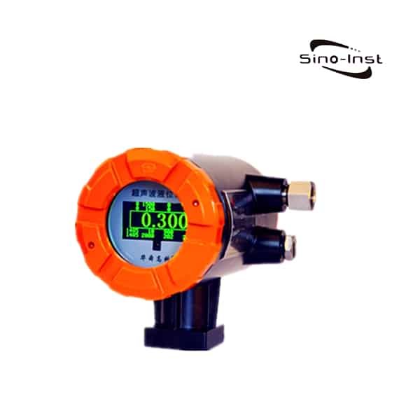
HS-2000 External Tank Level Sensor
External-mounted | non-invasive | 0–10 m range | ±0.5% — for closed pressurized tanks where internal mounting is not possible.

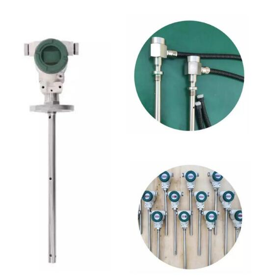
807 Low-Temperature Level Sensor
–40 to +80 °C | 0–6 m | IP68 | 4-20 mA — for outdoor and refrigerated tank applications where standard ultrasonic struggles.
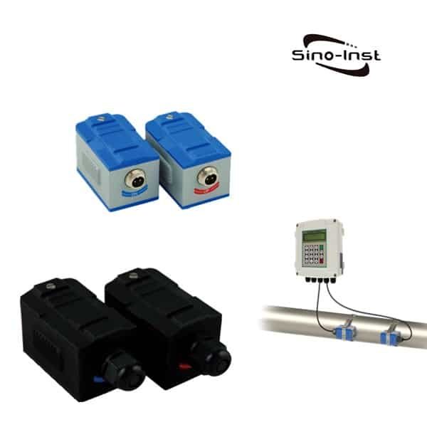
Ultrasonic Clamp-on Flow Meter
Transit-time | clamp-on | DN15–DN6000 | ±1% — companion ultrasonic technology for pipe flow when tank level isn’t the answer.
For sizing, sensor selection, and a tank-specific install drawing, contact our engineering team using the form below. Send the tank height, diameter, contents, mounting nozzle size, and any photos of the top of the tank — we typically reply with a recommended sensor and mounting plan within one business day.
FAQ
What is the blanking distance of an ultrasonic level transmitter?
The blanking distance, or dead zone, is the area directly in front of the transducer where no measurement is possible because the transducer is still vibrating from the transmit pulse. Typical values: 100 mm for a 200 kHz sensor, 300 mm for a 40 kHz sensor. The maximum liquid level must sit at least one blanking distance below the sensor face.
How high above the liquid should an ultrasonic level sensor be mounted?
At a minimum, one blanking distance above the highest expected liquid level. For a 40 kHz sensor (300 mm blanking) on a tank that fills to 5.7 m, mount the sensor at 6.0 m. Add 100–200 mm safety margin for surface waves and turbulence.
Why does my ultrasonic level transmitter show “lost echo”?
Three most common causes: the sensor is tilted more than 2° off perpendicular, foam or floating crust is blocking the return echo, or an internal fitting (ladder, agitator, nozzle) sits inside the beam cone. Check perpendicularity with a bubble level first, then map the cone footprint for obstructions.
Can ultrasonic level transmitters work outdoors?
Yes, with three precautions: a sunshade above the transducer to limit thermal drift, a short stilling well to block wind and rain, and ensuring the temperature compensation is enabled (a 50 °C ambient swing introduces about 7% level error without compensation).
How do I calibrate an ultrasonic level transmitter?
Six steps: (1) set sensor model, (2) enter tank height as the 4 mA reference, (3) enter empty distance, (4) enter full distance as the 20 mA point, (5) run the echo map with the tank drained to mask fixed obstructions, (6) fill to a known level and verify against a sight glass — adjust span if error exceeds ±0.5% of range.
Request a Quote


Wu Peng, born in 1980, is a highly respected and accomplished male engineer with extensive experience in the field of automation. With over 20 years of industry experience, Wu has made significant contributions to both academia and engineering projects.
Throughout his career, Wu Peng has participated in numerous national and international engineering projects. Some of his most notable projects include the development of an intelligent control system for oil refineries, the design of a cutting-edge distributed control system for petrochemical plants, and the optimization of control algorithms for natural gas pipelines.