Magnetic Level Gauge Indicator: How It Works, Types, and When It Beats a Sight Glass

Updated April 24, 2026 by the Sino-Inst Engineering Team

A magnetic level gauge is a mechanical indicator that reads liquid level from the outside of a vessel using a magnetic float sealed in a bypass chamber. No power, no sight glass, no wetted electronics. It is what most oil, gas, and chemical plants now use in place of tubular sight glasses — especially above 150 psi or when the fluid is toxic, flammable, or opaque.

This guide covers how a magnetic level gauge works, the two indicator styles (roller and capsule), how it compares to a sight glass, and the transmitter and switch options you can bolt on without breaking the process seal.

Contents

How Does a Magnetic Level Gauge Work?

A magnetic level gauge works on the principle of communicating vessels: liquid in a bypass chamber sits at the same height as liquid in the main tank. Inside that chamber, a float containing a ring magnet rises and falls with the level. The float’s magnetic field passes through the non-magnetic chamber wall (typically 316L stainless) and flips an external indicator strip. You read the level from outside the pressure boundary.

Three physical principles are doing the work at the same time:

  • Communicating vessels — the bypass chamber is piped into the tank at two points, so levels equalize.
  • Archimedes’ buoyancy — the float’s density is set so it rides on the liquid surface, not in the vapor or submerged.
  • Magnetic coupling — the float’s ring magnet flips each indicator element (roller or capsule) as it passes.

Because the indicator and any transmitter are outside the chamber, they never touch the process. This is the single biggest reason the magnetic level gauge has displaced the tubular sight glass in modern plants.

What Are the Main Parts of a Magnetic Level Indicator?

Every magnetic level gauge is built from four parts:

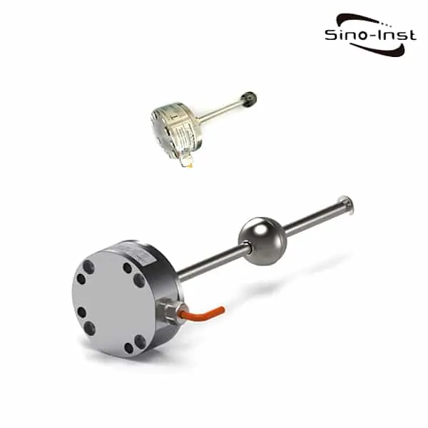
  1. Float chamber — a non-magnetic pipe (304/316L SS, Hastelloy, titanium) with flanged or threaded process connections. This is the pressure-bearing part. Rated to match the tank: typically 150#, 300#, or 600# ANSI.
  2. Float — a hollow cylinder with an embedded ring magnet. Density is matched to the lightest expected process fluid; the same float won’t work for both water and diesel.
  3. Indicator rail — the external strip you read. Either bi-colour rollers or a moving capsule behind a glass tube.
  4. Options — clamp-on magnetostrictive transmitter, reed-switch level alarms, heat tracing, steam jacketing, insulation.

What Are the Types of Magnetic Level Indicators?

Magnetic level indicators split two ways: by mounting and by indicator style.

By mounting:

  • Side-side (bypass, external cage) — two nozzles on the tank side. The most common configuration. Serviceable without tank entry.
  • Top-mounted — chamber hangs inside the tank. Used when side nozzles are not available or the fluid is clean enough to not foul the chamber.
  • Top-bottom — one top nozzle, one bottom nozzle. Used for tall atmospheric tanks where you can’t get two side connections.

By indicator style: roller (bi-colour flags) or capsule (shuttle). See the next section.

Roller vs Capsule Indicator: What’s the Difference?

Roller and capsule indicators do the same job but fail differently. The roller style is better for high-vibration service; the capsule style is better for cold climates and dirty installations.

IndicatorHow It Shows LevelBest ForWatch Out For
Bi-colour rollersEach 10 mm roller flips 180° as the float passes; red above / silver below the liquid lineStandard service, long-distance readability (visible at 30+ m)Individual rollers can stick after years of vibration; easy to field-swap
Capsule (shuttle)A single bi-colour capsule tracks the float inside a glass tubeCold outdoor service (no rollers to freeze), dusty plantsIf the capsule drops off during shock, it won’t track until manually reset

Rollers are the default for 95% of installations. Order the capsule style only if you are in Arctic service, a food plant with frequent washdowns, or somewhere rollers would collect dust.

Magnetic Level Gauge vs Sight Glass: Which Is Better?

For pressurized, toxic, corrosive, or dark fluids, a magnetic level gauge is safer and easier to read than a tubular or reflex sight glass. Sight glass still wins on cost for clean water service at low pressure — nothing else. Here is the side-by-side:

CriterionMagnetic Level GaugeTubular / Reflex Sight Glass
Pressure boundaryMetal chamber, matched to piping ratingGlass — can shatter; requires gauge glass class per ASME
Readability30+ m (red/silver contrast)3 m (you need to stand at the tank)
Leak pathZero moving seals on the process sideGasket leaks, glass-to-metal seal maintenance
CleaningChamber interior is internally bypassed — no fouling on the readoutGlass fouls with scale, coating, opaque fluids
Transmitter add-onClamp-on magnetostrictive or reed switches anytimeSeparate instrument required
Initial cost2–4× sight glass at the same pressure ratingLowest initial cost
5-year TCOLower (no gasket/glass replacement, no cleaning)Higher when you count maintenance shutdowns
Hazardous serviceSafe — metal pressure boundaryRisk of fugitive emission on glass failure

The short rule: sight glass for open water tanks and low-pressure clean service; magnetic level gauge for everything else, especially hydrocarbons, steam drums, and anything over 150 psi.

Can You Add a Transmitter or Switch to a Magnetic Level Gauge?

Yes — and this is the main reason MLGs have spread in DCS-controlled plants. Because the float carries a magnet, you can clamp any magnetostrictive or reed-switch transmitter to the outside of the chamber and pick up the same float position electronically. No wetted parts, no process intrusion, and you can add or remove the transmitter during operation.

Three common add-ons:

  • Magnetostrictive transmitter — clamps to the chamber; 4–20 mA HART output, ±0.05% FS. This is the standard choice when you need the level on the DCS. See our magnetostrictive level transmitters guide for the selection matrix.
  • Reed-switch level alarms — external clamp-on switches at hi/lo/hi-hi/lo-lo points. SPDT relay output, no power on the process side.
  • Guided wave radar — mounted in parallel on the same bypass chamber for SIL-rated redundant measurement. We cover the calibration on our guided wave radar calibration guide.

Where Does a Magnetic Level Gauge Fail?

A magnetic level gauge has three real failure modes, and every field engineer has seen each one at least once:

  1. Wrong float density. If the process fluid density changes (mixed-phase service, interface measurement, seasonal temperature), the float sinks or rides too high. Specify the float for the minimum expected SG. For interface service, specify a float that floats on the heavier phase.
  2. Ferrous particles stuck to the float. In wastewater, pulp stock, or any service with magnetite scale, iron particles accumulate on the float magnet and add mass until the float hangs up. Install a Y-strainer upstream of the bypass or switch to a non-magnetic measurement.
  3. Freezing / wax solidification in the chamber. The bypass chamber has dead legs. In cold climates, heat-trace and insulate the chamber. For waxy crude, add steam tracing at a minimum 70 °C bath.

None of these are design flaws — they are specification mistakes. Get the float and the tracing right on day one and an MLG will run for 20 years without calibration. For related troubleshooting on bypass-chamber instruments, see our stilling wells for radar level primer.

Installation Checklist

  • Side process connections centered on the MIN and MAX measuring points — the chamber must span the full indicating range.
  • Isolation valves and a drain/vent on each process connection — needed for hydrotest and float removal.
  • Chamber installed vertical within 1° — a tilted chamber makes the float drag on the wall.
  • No ferromagnetic pipe or rebar within 150 mm of the indicator rail — external magnetic fields will flip rollers the wrong way.
  • Match the float to the lowest fluid density expected. For interface work, match to the heaviest.
  • For steam service, always steam-jacket the chamber. A cold chamber on a hot-steam drum will condense and indicate false.
  • Before commissioning: lift the float with a magnet from outside and confirm every roller flips smoothly over the full range.

Related Sino-Inst Level Products

When an MLG alone is not enough — typically when you need an analog signal to the DCS or redundant level measurement — these three Sino-Inst instruments are the usual pairings:

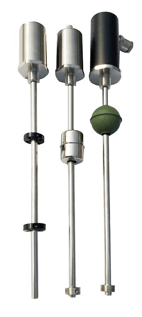
SI-100 Magnetostrictive Level Transmitter

SI-100 Magnetostrictive Level Transmitter

Rigid probe, ±0.03% FS, 316L wetted parts. Clamp a chamber-mount variant alongside an MLG to turn visual readout into a 4–20 mA HART signal without breaking the process seal.

SIRD70 Guided Wave Radar

−40 to 250 °C, unaffected by foam or vapor. Mount on a parallel nozzle for SIL-rated redundancy with the MLG doing visual backup.
SI-2116 Magnetostrictive Level Sensor

Integral flange-mount, interface capable. Good choice when you need both total level and oil-water interface from one instrument.

FAQ

How accurate is a magnetic level gauge?

The visual readout is accurate to about ±10 mm, limited by roller pitch. Add a magnetostrictive transmitter for ±0.03% FS (typically ±1 mm on a 3 m range). The MLG itself does not drift because it is mechanical.

Can a magnetic level gauge measure interface?

Yes, with two floats of different density — one rides on the light phase, one on the heavy phase. Each has its own indicator rail or transmitter channel. Interface MLGs are common on oil-water separators and amine flash drums.

What is the maximum pressure and temperature for a magnetic level gauge?

Standard units handle 600# ANSI (about 100 bar) and up to 450 °C with an insulated/jacketed chamber. Above these ratings, specify forged body and Inconel 625 floats — available but with 8–12 week lead times.

Does a magnetic level gauge need calibration?

The mechanical indicator does not — it is a 1:1 display of float position. Calibration applies only to the bolted-on transmitter or switches, and only during commissioning or after a float swap.

Can I use a magnetic level gauge on a plastic or FRP tank?

Yes. The chamber is a separate metal part connected via isolation valves; the tank material is irrelevant. Common in FRP acid tanks where a metal chamber with Hastelloy or titanium wetted parts is the only durable option.

Will the magnetic field affect other instruments nearby?

The float magnet is weak outside the chamber (a few gauss at 150 mm). It will not disturb electronic instruments at normal installation distances. Avoid mounting a compass or Hall-effect proximity switch within 300 mm of the indicator rail.

How long does a magnetic level gauge last?

20–30 years in clean service. The usual maintenance item is the float — after a decade the seam welds can fatigue. Budget a spare float during the initial purchase; swap during the next turnaround.

Need a Magnetic Level Gauge Quote?

Send us your tank parameters (fluid, SG, pressure, temperature, connection size, span) and we will return a chamber specification with material selection and transmitter options within one business day. Our engineers have 15+ years building MLGs for steam drums, hydrocarbon separators, amine units, and cryogenic tanks.

Request a Quote

Please enable JavaScript in your browser to submit the form

Wastewater Level Sensor for Septic Tanks and Sewage Holding Tanks: Selection and Installation

Updated: April 23, 2026

Septic tanks, sewage holding tanks, and lift station wet wells are the dirtiest service for any level sensor. Solids settle on the bottom. Grease and FOG (fats, oils, grease) form a scum layer on top. Hydrogen sulfide attacks anything with brass or copper. Wash-water pumps cycle the level so fast that point switches chatter. The right sensor is rarely the cheapest — but the cheap sensor fails in 6 months and shuts down the lift pump on a Sunday night. This guide walks through which sensor type fits which wastewater application, the installation rules that keep them alive, and the maintenance pattern that operators actually follow. For sensor-by-application selection on buried tanks, our underground tank level indicator guide for fuel, water and septic tanks.

Contents

Which Level Sensor Should I Use for a Septic or Sewage Tank?

For most septic and sewage tanks, a submersible hydrostatic level transmitter with a flush-diaphragm sensor is the right choice. It sits at the bottom of the tank, measures the head of liquid above it, and outputs a continuous 4-20 mA signal proportional to depth. It does not care about scum, foam, or vapor — only about how deep the liquid sits above its diaphragm.

For pump-cycling control where you only need start/stop signals (lift station, pump-out trigger), a multi-point float switch system is cheaper and simpler. For deep concrete vaults and very fouled service, a non-contact ultrasonic or radar mounted in the manhole avoids ever pulling a probe out. The deciding factors are tank depth, fouling severity, whether you need continuous or point measurement, and access for maintenance.

What Makes Wastewater Level Hard to Measure?

Wastewater is not a uniform liquid. It is three layers stacked in the same tank. For potable or industrial water tanks, the equivalent selection guide is water tank level sensors.

  • Sludge layer (bottom). Settled solids, sand, fecal matter. Builds up over months.
  • Liquid layer (middle). The flowing supernatant. This is what the level sensor needs to track.
  • Scum layer (top). Grease, fats, undigested floating material. Often 100-300 mm thick on septic tanks.

Each layer attacks sensors differently. The sludge buries probes inserted from the bottom. The scum coats anything inserted from the top, eventually sealing off ultrasonic transducers and radar antennas. The liquid itself contains H₂S in concentrations that destroy bronze and brass fittings within weeks. On top of all that, lift station wet wells flood and drain in 30-second cycles when the pumps are running, making wave action and turbulence a constant noise source.

Three failure modes account for most wastewater sensor calls:

  1. Diaphragm fouling on submersible sensors. A small recess in front of the sensing diaphragm fills with grease and the pressure no longer transmits. The reading freezes.
  2. Acoustic absorption on ultrasonic sensors. Heavy foam or thick scum absorbs the ultrasonic pulse and the sensor either gives no echo or locks onto the foam surface instead of the liquid.
  3. Cable damage on float switches. The cable rubs against the tank wall as the float swings, and the abrasion exposes copper to H₂S. Float fails to switch within a year.

Sensor Types Compared for Wastewater Service

Sensor TypeBest ForOutputTypical LifeMain Limitation
Submersible hydrostatic (flush diaphragm)Continuous level, septic and sewage holding tanks4-20 mA3-5 yearsDiaphragm fouling, needs occasional rinse
Submersible hydrostatic (vented cable)Open wet wells, deep tanks4-20 mA3-5 yearsVent must stay dry to avoid sensor damage
Multi-point float switchPump start/stop, high-level alarmDiscrete contacts1-3 yearsCable abrasion, no continuous reading
Ultrasonic non-contactDeep manhole vaults, clean service4-20 mA3-5 yearsFails on heavy foam or thick scum
80 GHz radar non-contactDifficult vapor service, raw sewage with foam4-20 mA5-7 yearsHigher capital cost, manhole mounting required
Capacitance probeCheap point switches in sumpsDiscrete contact1-2 yearsCoats with grease, false trips

The submersible hydrostatic transmitter wins for most installations because it is immune to foam, vapor, and turbulence. The pressure of the liquid above the sensor is what it sees, and that pressure is real regardless of what is happening at the surface. For a deeper general framework on tank selection across all liquid types, see our tank level sensor selection guide.

One nuance: if the tank is closed and pressurized (some commercial sewage systems), a vented submersible sensor will not read correctly because barometric pressure is no longer the reference. Use a sealed gauge sensor with separate static pressure compensation, or move to a non-contact radar.

Installation Rules That Save Sensor Life

Half of wastewater sensor failures come from poor installation, not bad sensors. These rules apply across all sensor types:

  • Mount away from inlet and pump suction. Falling sewage and pump wash create wave action and air entrainment. Place the sensor at least 1 metre from the inlet pipe and 0.5 metre from the pump intake.
  • Use a stilling well for submersible sensors. A 100 mm PVC pipe with holes drilled at the bottom isolates the sensor from wave action and traps less scum than the open tank does. Cap the top to keep larger debris out.
  • Hang sensors with stainless braided cable, not the signal cable. The signal cable is for signal. The mechanical load of the sensor goes on a separate stainless suspension. This protects the cable gland from fatigue cracks.
  • Route cable in conduit above the high-water line. Cable submerged in raw sewage absorbs water through micro-cracks within months. Conduit it out of the wet zone as soon as practical.
  • Specify Hastelloy or PVDF wetted parts on H₂S service. Standard 316L stainless pits in concentrated H₂S environments. For long life on heavy sewage, the body and diaphragm both need an upgrade.
  • Provide a wash-down nozzle. Most sites benefit from a 1/2" rinse line aimed at the sensor face that operators can manually open during routine cleaning.

For installations with float switches in addition to a continuous sensor, our float switch installation guide covers the spacing and cable-routing rules.

Maintenance and Cleaning Schedule

Wastewater sensors are not install-and-forget. Build a schedule into the work order system or the sensor will eventually drift, fail silently, and trip a high-high alarm at 2 a.m.

IntervalTaskReason
MonthlyVisual inspection, manual rinse if accessibleClear surface scum and fouling early
QuarterlyPull sensor, wash with detergent and warm waterRemove biofilm before it cements
AnnualCalibration check against a manual dipstickCatch slow drift before it affects pump cycling
AnnualInspect cable jacket and gland for cracksPrevent water ingress into sensor body
3-5 yearsReplace if drift exceeds 1% or visual damageAvoid catastrophic failure during peak load

One under-appreciated trick: log the daily min/max level reading. A submersible sensor with diaphragm fouling will gradually compress its operating range — the daily minimum starts to creep up by 50-100 mm before the sensor visibly fails. Spotting that drift in the historian gives you weeks of warning to schedule cleaning, instead of an emergency call-out.

Sizing the Sensor to Tank Geometry

The sensor range must cover the full operating depth plus margin. A common error is buying a sensor with the same range as the tank height, which leaves no room for over-fill events.

  • Tank max liquid depth: H meters
  • Sensor range: H × 1.25 meters minimum (water column)
  • Convert to pressure: 1 m H₂O ≈ 9.81 kPa

Worked example: A septic holding tank is 3.5 m tall. Specify a submersible sensor ranged 0-44 kPa (≈ 4.5 m H₂O), giving a 25% safety margin for surge events. Cable length: tank depth + 2 m for the cable gland and conduit transition above the manhole.

For tank applications outside the standard sewage range — high-temperature digesters, industrial waste streams — see our broader cooling tower and process tank level guide which covers similar fouling-resistant approaches.

Wastewater Level Sensors from Sino-Inst

Submersible Hydrostatic Level Transmitter

316L stainless body, flush diaphragm, 4-20 mA output. The standard sensor for septic and sewage holding tanks up to 30 m depth.

Wireless LoRa Level Sensor

Battery-powered hydrostatic sensor with LoRa wireless. Use on remote septic or rural lift stations where running cable is not practical.

Tank Level Sensor Selection Guide

Decision matrix by tank content and conditions. Use to compare hydrostatic, ultrasonic, radar, and float options for sewage, septic, and process tanks.

FAQ

What is the best level sensor for a septic tank?

A submersible hydrostatic transmitter with a flush diaphragm is the best continuous-level option. It is immune to scum, foam, and vapor — the things that defeat ultrasonic sensors in septic service. Pair with a high-level float switch for redundant alarming.

Will an ultrasonic sensor work on a sewage tank?

Sometimes, but not reliably. Heavy foam absorbs the ultrasonic pulse, and grease coats the transducer face. On clean lift stations with low foam, ultrasonic from the manhole works. On septic tanks with active digestion, expect frequent maintenance and missed echoes.

How do I keep the level sensor from clogging?

Three steps: install a flush-diaphragm sensor (no recessed cavity to fill), suspend it in a stilling well to reduce direct contact with debris, and provide a wash-down nozzle that operators can use during routine cleaning. Quarterly manual rinse extends life two to three years.

What material should a sewage level sensor be made of?

316L stainless body works for typical municipal sewage. For high-strength industrial waste or septic tanks with high H₂S concentrations, upgrade to Hastelloy C-276 or PVDF-coated bodies. Avoid brass, bronze, and copper anywhere on the sensor or fittings.

Can I use the same sensor for a septic tank and a sewage holding tank?

Yes if both tanks are open vented. The same submersible hydrostatic transmitter works for both. If the holding tank is sealed and pressurized, switch to a sealed-gauge sensor or a non-contact radar from the tank top.

How long does a wastewater level sensor last?

Three to five years for a properly installed and maintained submersible hydrostatic sensor. Without quarterly cleaning, expect 12-18 months. Float switches typically last 1-3 years before cable abrasion or contact wear forces replacement.

Get a Wastewater Level Sensor Quote

Send us your tank dimensions, type of waste (septic, sewage, industrial), pump cycling pattern, and access constraints. We’ll spec a sensor model, body material, and install drawing — usually within one business day.

Request a Quote

Please enable JavaScript in your browser to submit the form

Tank Level Sensors: How to Choose by Tank Content (Decision Matrix)

Updated: April 16, 2026 | By Sino-Inst Engineering Team

Most tank level sensor guides start with the sensor — radar, ultrasonic, hydrostatic, capacitance — and tell you what each one does. That is the wrong way around. The fluid you are measuring eliminates more than half the sensor types before you even think about budget. This guide flips the lookup: pick your tank content first, and the right sensor narrows to one or two choices. Use it for new specifications or to second-guess an existing installation that keeps failing.

Contents

Quick decision matrix: tank content to sensor

Tank contentFirst-choice sensorBackup choiceAvoid
Clean water (tower, cistern, well)Submersible hydrostaticRadar (80 GHz)Capacitance
Diesel / fuel oilMagnetostrictiveServo gaugeUltrasonic (vapor)
Strong acids / causticsGuided wave radar (PFA-coated)Bubbler / DPHydrostatic submersible
Slurry, sludge, mud80 GHz radar (non-contact)DP transmitter with diaphragm sealsFloat, capacitance
Foamy or stratified liquidsGuided wave radarMagnetic level gaugeUltrasonic, free-space radar
Hot oil / asphalt (>200°C)Guided wave radar (HT probe)Servo gaugeSubmersible, capacitance
Food, beverage, pharmaSanitary radar (3A / EHEDG)Sanitary capacitanceBubbler, contact float
LNG, LN2, cryogenicMagnetostrictive (cryo seal)Servo with floatCapacitance, hydrostatic
Solid powders / pellets80 GHz radar with dust shieldGuided wave radarUltrasonic, hydrostatic
Overflow / dry-run point onlyVibrating fork (tuning fork)RF admittance, float switchContinuous transmitter

Step 1: Define what’s in the tank

“Liquid” is not a content category. Conductive vs non-conductive matters for capacitance probes. Dielectric constant matters for radar. Foam matters for ultrasonic. Vapor pressure matters for any non-contact tech. Before specifying anything, write down these six properties of your fluid:

  • Density (kg/m³ at operating temperature)
  • Dielectric constant εr (water = 80, hydrocarbons = 2-4, plastics = 1.5-3)
  • Conductivity (water with salts = high, distilled water = low, oils = none)
  • Viscosity at operating temperature
  • Foam tendency (yes / no / sometimes)
  • Vapor or condensate above the surface (steam, solvent vapor, etc.)

If you cannot get this from the SDS, ask the process engineer who designed the tank. Specifying a level sensor without these numbers is what produces the field calls we get six months later.

Step 2: Continuous reading or point switch?

Continuous transmitters give you a 4-20 mA reading anywhere in the tank’s range. Point switches just close a contact at one fixed level. They cost different orders of magnitude and they fail differently.

NeedUse continuousUse point switch
Inventory trackingYesNo
PID loop / blending controlYesNo
Pump start / stop onlyOptionalYes (cheaper)
Overflow safety / dry-run cutoutNo (use both)Yes (SIL-rated)
Custody transferYes (servo or magnetostrictive)No
Budget under $200Rare (hydrostatic + display)Yes (float, fork)

For pump control, a continuous transmitter feeding the PLC plus an independent float switch as backup is a far more reliable arrangement than two transmitters in voting. The float switch covers the failure mode where the transmitter fails high or stuck. For pump-only switching, see our float switch wiring guide.

Clean water and potable storage

Submersible hydrostatic transmitters are the default. The probe sits at the tank bottom, measures the pressure of the water column above it, and outputs 4-20 mA proportional to depth. Accuracy is ±0.1% FS for quality units, the cable doubles as a vent (atmospheric reference), and there are no moving parts to wear out.

For potable water, choose a NSF/ANSI 61 certified probe. For elevated towers (over 15 m head), check the cable’s vent tube doesn’t sag and form condensate traps — a saturated vent tube reads erratically. The non-contact alternative is 80 GHz radar mounted on the top, which avoids any in-tank hardware but costs roughly 3x.

Fuel, diesel and lubricating oil

Magnetostrictive transmitters dominate this category because hydrocarbons have stable density, low foam, and the float-on-stem principle gives the ±1 mm accuracy that fuel inventory needs. The same probe can carry up to 8 RTDs for ATG (automatic tank gauging) compliance. For an underground or buried tank with restricted top access, the flexible-cable version of the same technology installs through a 2″ riser.

Avoid ultrasonic on diesel — vapor density above the liquid changes the speed of sound, which throws the level reading off by 1-3% as temperature swings. Use it only on water; on fuel it always disappoints in field service.

Acids, caustics and corrosive chemicals

Guided wave radar with a PFA or PTFE-coated probe is the safe specification for sulfuric acid, sodium hydroxide, hydrogen peroxide, and other aggressive chemicals. The radar pulse travels along the probe regardless of dielectric constant, vapor density, or foam. The PFA coating isolates everything but the probe end from the medium.

For storage tanks where in-tank hardware is forbidden by safety policy, fall back to a bubbler system (DP transmitter with a purge gas line). Bubblers are old technology but they are bulletproof on the most aggressive chemicals — nothing wetted is in contact with the tank except the dip tube.

Slurry, sludge and abrasive media

Anything in contact with mining slurry, raw sewage, paper pulp, or cement gets coated, eroded, or both. The default specification is non-contact 80 GHz radar mounted above the tank with a 6° narrow beam and a self-cleaning antenna. Build-up on the antenna is what kills slurry radars; the 80 GHz devices have small antenna footprints and air-purge ports for periodic cleaning.

If radar isn’t an option (sealed tank with no top opening), DP transmitters with remote diaphragm seals on the tank’s high and low pressure taps work — but every cleaning cycle becomes a maintenance event. Avoid floats and capacitance in slurry; both will be disabled within a month.

Food, beverage and pharmaceutical

3A and EHEDG certifications are non-negotiable. Sanitary radar is the dominant choice — flush-mount on a tri-clamp connection, no crevices for product to harbor in, full CIP/SIP cleanability. For low-cost agitated tanks, sanitary capacitance probes work for water-based products but struggle when fat content varies (changing dielectric).

Avoid bubblers (purge gas in product is unacceptable) and avoid contact floats (cleaning impossible).

Cryogenic and extreme temperature

Below -40°C and above 200°C is where most general-purpose level sensors quietly drift out of spec. Magnetostrictive transmitters with cryogenic seal extensions work down to liquid nitrogen temperatures. For LNG bullets, a servo gauge with a stainless float is the API standard.

For molten sulfur, asphalt, and hot oil up to 400°C, guided wave radar with a high-temperature antenna assembly is the only practical continuous solution. Hydrostatic submersibles are not rated; capacitance probes drift severely with temperature. For more on hot-tank installation specifics, see our high-temperature radar level guide.

The common mistake: defaulting to ultrasonic

Ultrasonic level transmitters are cheap, non-contact, and look like a universal solution. They are not. Ultrasonics measure the time-of-flight of a sound pulse to the liquid surface and back. Anything that disrupts the air column between the sensor and the surface throws the reading off.

  • Vapor: any solvent vapor, condensing steam, or even rapid temperature gradients change the speed of sound by several percent.
  • Foam: the pulse reflects off foam, not the actual liquid surface.
  • Dust or fog: attenuates the signal until it reads “lost echo.”
  • Stratified temperature: outdoor tanks in summer have a cool layer near the liquid and hot air at the top — a refraction lens that bends the pulse.

Ultrasonics are appropriate for clean water in open atmospheric tanks at stable temperatures. That is a small slice of real applications. When in doubt, switch to 80 GHz radar — same non-contact installation, immune to all the conditions above, costs about 1.5x.

Featured tank level sensors

Submersible Hydrostatic (Water)

SMT3151TR submersible hydrostatic level transmitter with 316L stainless probe. Drops straight into wells, reservoirs and storage tanks — 4-20mA output for continuous level monitoring.

Magnetostrictive (Fuel)

Magnetostrictive level transmitter with ±1 mm resolution for high-accuracy tank gauging. Preferred choice on fuel depots, API terminals and chemical inventory measurement.

DP Transmitter (Chemical)

DP transmitters measure pressure difference across gas, liquid or steam. 4-20mA / 0-5V output drives liquid level, density and flow loops across process plants.

FAQ

What is the most accurate tank level sensor?

Magnetostrictive transmitters reach ±0.1 mm in custody-transfer configurations, the highest of any commercial tank level technology. Servo gauges (Honeywell Enraf, Endress+Hauser Proservo) match this for tall storage tanks. Hydrostatic and radar are typically ±2-5 mm at best.

What is the cheapest reliable tank level sensor?

For continuous reading on water, a basic submersible hydrostatic transmitter runs $150-300 and works for 5+ years with no maintenance. For point-only level switching, a cable-tilt float switch is under $40. Don’t pay more for fancier tech if your application doesn’t need it.

Can one sensor replace multiple float switches?

Yes. A continuous transmitter feeding a PLC can derive any number of virtual setpoints in software — high-high alarm, high pump-stop, low pump-start, low-low cutoff — from one 4-20 mA reading. The trade-off is single point of failure; most safety systems still keep one independent float switch as a backup.

Do I need radar or ultrasonic for an outdoor tank?

Radar. Ultrasonic readings drift in summer when the air column above the liquid stratifies into hot upper / cool lower zones, and they fail outright in heavy rain or fog. 80 GHz radar is unaffected by atmospheric conditions.

How do I measure level in a tank with foam on top?

Guided wave radar — the radar pulse travels along a probe into the foam and reflects off the actual liquid surface below it. Free-space radar and ultrasonic both reflect off the foam itself and read incorrectly. The other option is a magnetic level gauge with an external chamber: foam stays in the main tank, the chamber sees clean liquid.

What sensor works for solid material in tanks (powders, pellets)?

80 GHz radar with a dust-shielded antenna is the modern default. Guided wave radar with a single rope probe works for tanks under 30 m where the rope can swing freely. Avoid ultrasonic — solids have an irregular angle of repose that scatters the pulse.

How often should tank level sensors be calibrated?

Hydrostatic and DP transmitters drift slowly and benefit from annual zero/span verification. Magnetostrictive and servo gauges measure time-of-flight and don’t drift mechanically — every 2-3 years is usually enough. Radar gauges have no moving parts and need calibration only when something physically changes inside the tank (new internals, repositioned nozzle).

Need help specifying for your tank?

Send tank dimensions, fluid SDS, operating temperature/pressure, and any agitation or foam characteristics. We’ll spec a primary and a backup option, with an honest reason if the lowest-cost answer is the right one.

Request a Quote

Please enable JavaScript in your browser to submit the form

How Does a Capacitive Liquid Level Sensor Work? (Engineer’s Guide 2026)

Updated: April 15, 2026

A capacitive liquid level sensor detects level by measuring the capacitance change between a probe and the tank wall (or a second probe) as the liquid rises or falls. The liquid acts as the dielectric — its dielectric constant determines how much capacitance changes per centimeter of level. That’s the whole working principle in one sentence.

What matters in the field is knowing when this technology works well (oils, water, most chemicals, slurries) and when it doesn’t (varying dielectric, heavy coating, high-purity water). This guide walks through the physics, sensor types, calibration, and the dielectric-constant numbers you actually need to size a probe.

Contents

How Does a Capacitive Liquid Level Sensor Work?

The sensor acts as one plate of a capacitor; the tank wall or a second rod acts as the other plate. Liquid between them is the dielectric material. When level rises, more of the probe is submerged, dielectric material replaces air (εr of water is 80 vs air’s 1), and capacitance jumps.

The transmitter converts that capacitance change into a 4–20 mA or digital signal proportional to level. The equation:

C = (ε0 × εr × A) / d

Where ε0 is the vacuum permittivity, εr is the relative dielectric constant of the liquid, A is the submerged electrode area, and d is the gap. Because εr is the only variable that depends on the medium, the sensor must be calibrated to the specific liquid.

What Are the Main Types of Capacitive Level Sensors?

Four probe configurations cover almost every tank scenario.

  • Bare rod (single probe, metal tank). The rod and the conductive tank form the capacitor. Simplest and cheapest. For conductive liquids like water, the rod must be insulated.
  • Insulated rod. PTFE or PFA jacket prevents shorting in conductive media. Standard for water, acids, and alkalis.
  • Dual-rod (coaxial). A second rod replaces the tank wall — used in plastic or fiberglass tanks where there’s no grounded reference.
  • RF admittance. Adds a driven guard to cancel out coating effects on the probe. Used on sticky liquids like slurries, glue, and chocolate. See our RF admittance level sensor guide.

What Dielectric Constants Work with Capacitive Sensing?

Capacitive sensors work reliably when the liquid’s dielectric constant is ≥1.8 and stable. Below that, capacitance change per cm is too small to measure reliably. If εr varies with temperature or composition, calibration drifts.

Liquidεr (approx.)Capacitive sensing
Air / vapor1.0Reference
Gasoline, kerosene2.0Marginal — needs sensitive electronics
Diesel, fuel oil2.1–2.3Good
Lubricating oil2.2–2.8Good
Vegetable oil3.0Good
Alcohols (ethanol)24Excellent
Water (tap)80Excellent — requires insulated probe
Aqueous acids/bases40–80Excellent — requires insulated probe

Do not use capacitive sensing on liquids with unpredictable εr — examples include variable oil–water emulsions and slurries of changing solids content. Use guided wave radar or float-based measurement instead.

What Are the Advantages and Disadvantages?

Short answer: capacitive is a low-cost, rugged workhorse, but it’s sensitive to medium properties and probe coating.

AdvantagesDisadvantages
No moving parts — long service lifeNeeds stable dielectric constant
Works in pressurized and high-temp tanks (to 200 °C, 40 bar)Coating on probe shifts calibration
Compact — fits small tanks where radar doesn’tMetal tank required for single-rod types
Low cost: $150–$600 per sensorMust be recalibrated if liquid changes
Accuracy ±1% of full scaleFoam and vapor can affect top of range

How Do You Calibrate a Capacitive Liquid Level Sensor?

Two-point calibration handles most capacitive sensors. Do it with the actual process liquid, not water. For general calibration procedures across flow and level instruments, see our calibration procedures guide.

  1. Empty the tank. Set the low (4 mA / 0%) point. This captures probe-to-tank baseline capacitance.
  2. Fill to 100% of measuring range. Set the high (20 mA / 100%) point.
  3. Verify at midpoint. Fill to 50% and check reading is 12 mA ±1%. If off, check for probe coating or partial air gap.
  4. Log ambient temperature. εr of many oils changes 0.1% per °C. For wide temperature swings, use a transmitter with temperature compensation.

A common field mistake is to calibrate with water when the tank will hold oil. The dielectric constants differ by a factor of 30, and the sensor reads nonsense until you recalibrate.

Capacitive vs Float vs Ultrasonic: Which to Pick?

Capacitive wins on cost and durability in small-to-medium tanks with stable liquids. Float meters win where power or electronics aren’t available. Ultrasonic wins on non-contact measurement in open tanks.

CriterionCapacitiveFloatUltrasonic
Contact with liquidYesYesNo
Moving partsNoYesNo
Handles foam / vaporFairFairPoor
Handles sticky / coating liquidsPoor (RF admittance: Good)PoorGood
Accuracy±1% FS±3–5% FS±0.5% FS
Typical cost (1 m range)$150–$600$50–$300$300–$800

Featured Capacitive Level Sensors

Capacitance Level Transmitter

SI700 RF capacitance level transmitter for continuous and point level detection in liquids and solids. Resists coating, condensation and vapour layers — reliable where radar struggles.

Capacitive Water Level Sensor

Contact and non-contact capacitive water level sensor for storage tanks, wells and corrosive liquids. Resists temperature, humidity and conductivity drift for reliable readings where floats fail.

Capacitive Level Switch

Capacitive (RF) level sensor for liquid, solid and interface measurement. Handles high-temp, corrosive and easy-to-crystallise media with anti-clogging probes and 4-20mA output.

FAQ

Can a capacitive level sensor measure both liquids and solids?

Yes, for solids with dielectric constant ≥1.8 — grain, plastic pellets, cement powder all work. The accuracy is lower (±3%) because dielectric varies with bulk density.

Does probe length affect accuracy?

Longer probes give higher capacitance change per unit level, which improves resolution. Up to a point — probes over 4 m may need a high-sensitivity transmitter. Never cut a factory probe in the field; it changes the calibration curve.

What makes RF admittance different from standard capacitive?

RF admittance uses a driven guard electrode that cancels out capacitance caused by coating on the probe. Standard capacitive sensors drift when a residue builds up; RF admittance ignores it. Use RF admittance on sticky liquids and heated oils.

Does a capacitive sensor work with pure deionized water?

Yes, but with reduced accuracy. DI water’s dielectric constant is the same (80), but its low conductivity causes response instability. For ultra-pure water service, conductivity-based or ultrasonic water level sensors are more reliable.

Is capacitive level sensing safe for hazardous areas?

Yes. Intrinsically safe and explosion-proof versions are available with ATEX and IECEx certifications. Specify Ex ia for flammable liquid tanks and Ex d for vapor spaces.

How long does a capacitive level sensor last?

With no moving parts, expected life is 10–15 years in normal service. PTFE-jacketed probes in aggressive chemicals last 5–10 years before coating degradation forces replacement.

Need to confirm whether capacitive is the right fit for your tank? Send us the liquid, probe length, and tank material. Our engineers will recommend the right probe type and output, plus a quote — usually within 24 hours.

Request a Quote

Please enable JavaScript in your browser to submit the form

Float Switch for Water Tank: Wiring Diagrams + Troubleshooting

Updated: April 16, 2026 | By Sino-Inst Engineering Team

A float switch on a water tank is just a mechanical contact in your pump’s power loop. When the float rises, the contact opens (or closes); the pump stops (or starts). 90% of the calls we get about float switch failures are not failed switches at all — they are wiring mistakes, wrong terminal selection (NO vs NC), or pumps drawing more current than the switch’s contacts can handle. This page walks through the three wiring patterns that cover most water tank applications and a step-by-step fault-finding flow.

Contents

Quick wiring answer (read this first)

For an emptying tank (sump pump that runs when level rises): use the Normally Open (NO) contact. Float floats up → NO closes → pump runs.

For a filling tank (cistern pump that runs when level drops): use the Normally Closed (NC) contact. Float drops → NC stays closed → pump runs to refill.

If the float switch is rated for less amperage than your pump’s full-load current (FLA), wire it to a contactor or pump relay coil instead of directly to the motor. This is covered in Scenario C below.

How a float switch interrupts the pump circuit

A float switch is a single-pole device. Inside the float housing is either a mercury bulb (older designs), a steel ball that rolls into a microswitch (modern tilt-type), or a sealed reed switch on a stem with a magnet inside the float. All three behave the same way at the terminals: there is a common (C) wire and either a normally open (NO) or normally closed (NC) wire — sometimes both, in a single-pole double-throw (SPDT) switch.

The float switch is wired in series with one leg of the pump’s power supply. Power flows from the line, through the switch contact, through the pump motor, and back to neutral. Open the contact and the pump loses power. There is no logic, no controller, no signal — it is the same as a wall light switch with a heavier rating.

Cable-tilt floats use the cable itself as the pivot. The length of free cable below the cord grip sets the differential between pump-on and pump-off levels. For tank gauging applications that need continuous level (not just on/off), see our guide on tank level sensor types and selection.

NO or NC: choosing the right terminal for fill or empty

Read the application backwards. Decide first what state the pump must be in when the tank is full, then pick the contact that gives you that state.

ApplicationPump should run whenFloat position when runningUse terminal
Sump / sewage / lift pumpTank is filling up (empty it)Float UPNO (closes when float rises)
Cistern / make-up waterTank is draining (refill it)Float DOWNNC (closes when float drops)
High-level alarm onlyLevel is dangerously highFloat UPNO to alarm coil
Low-level dry-run cutoutLevel is too low (must STOP pump)Float UP (cuts off when float drops)NO to interlock chain

If your float switch only has two wires, the manufacturer has pre-wired it for one mode. Cable-tilt floats labeled “pump down” or “drain” are NO; floats labeled “pump up” or “fill” are NC. Checking with a multimeter on continuity is faster than reading the data sheet — flip the float by hand and watch the beep.

Scenario A: single float driving the pump directly

This is the simplest setup. Use it when the pump’s full-load amperage is below the float switch’s contact rating (typically 10A at 250VAC for a quality cable-tilt float, 5A for cheap reed-stem types).

  1. Cut the line (hot) wire of the pump cord, not the neutral. Cutting neutral leaves the pump energized when the float opens — a shock risk during service.
  2. Strip both ends of the cut and one lead of the float switch. Junction them in a watertight box outside the tank if possible.
  3. Connect line-in → float common; float NO (or NC, per the table above) → pump line-in.
  4. Cap or insulate the unused float lead (NC if you used NO, and vice versa). A floating bare conductor in a damp pump pit is the #1 reason these systems fail.
  5. Bond the pump’s green/ground wire all the way through to the supply ground. The float switch never interrupts ground.

Cable-tilt models (the egg-shaped floats on a cord) self-set their pump-on / pump-off differential by the length of cord below the cable clamp. A short tether (4–6 inches) gives a tight ±3 inch level band; a long tether (12–18 inches) gives a 12+ inch band. Long tethers reduce pump cycling, which is what kills small submersibles.

Scenario B: dual float for fill and high-level cutoff

Use two floats when one float can’t safely handle both the start command and a backup safety cutoff. Common cases: cisterns where overflow would damage the building, sewage tanks where a stuck float means flooding, fuel transfer systems.

  • Lower float (working float): wired to start/stop the pump on its normal differential band.
  • Upper float (high-level cutoff): wired in series with the working float on a fill system, OR to an alarm/shutdown circuit on a drain system. If the working float jams, the upper float overrides.

For a fill cistern: line → upper-float NC → lower-float NC → pump line-in. Both floats must be DOWN (NC closed) for the pump to run. The pump stops as soon as either float rises. The upper float should be set 4–6 inches below the overflow line so it has time to act before water spills.

For a sump pump: lower float NO drives the pump; upper float NO drives a 12V alarm or an internet-connected sensor. The upper float never touches the pump circuit — its only job is to tell you the working float failed.

Scenario C: float through a contactor for large pumps

If your pump’s nameplate shows more than 8–10 amps, do not run pump current through the float switch contacts. Contact welding is what kills float switches in heavy applications: every start arc burns a little metal, and after a few hundred cycles the contacts fuse closed and the pump runs forever.

The fix is a contactor (motor starter relay) sized to the pump. The float switch only carries the contactor coil current — typically 100–300 mA at 24V or 120V — which is well within any float switch’s rating. The contactor’s heavy contacts handle the pump load and can be replaced as a wear part.

  1. Wire the float switch to the contactor coil terminals (A1, A2). Float NO in series with the coil hot leg.
  2. Wire the pump motor leads to the contactor’s load contacts (T1, T2, T3 for 3-phase).
  3. Add a thermal overload block downstream of the contactor sized to the pump’s FLA × 1.15.
  4. If you need remote start/stop, wire a HAND-OFF-AUTO selector switch in parallel with the float across the coil.

This is also the right approach for explosion-proof installations. The float can be intrinsically safe (low energy, in the hazardous area), the contactor sits in a non-hazardous panel. For a deeper look at high-current and DP-style installation rules, see our DP transmitter installation guide.

Five wiring mistakes that burn out pumps and switches

  • Switching the neutral, not the line. Pump stays energized when float opens; the casing can become live if internal insulation fails.
  • Picking the wrong NO/NC terminal. Pump runs continuously or never starts. Test with a multimeter before powering up.
  • Tether too short on a cable float. Pump cycles every 30 seconds, motor windings overheat in days.
  • Float allowed to rest against the tank wall. Float wedges, never tilts. Always install with at least 6 inches of free swing.
  • Running 15A pump current through a 10A float contact. Contacts weld closed; pump runs the well dry. Add a contactor (Scenario C).

Troubleshooting flow when the pump won’t stop or won’t start

Run this in order. The first three steps catch about 80% of float switch problems without removing the switch from the tank.

  1. Check power at the pump. Disconnect the float from the circuit (jumper across float wires) and try the pump. If the pump still won’t run, the problem is upstream of the switch — breaker, cord, motor.
  2. Manually flip the float. With the system de-energized, lift the float through its full travel. You should hear a faint click (microswitch) or feel a snap (mercury). No sound = stuck switch, replace.
  3. Continuity test at the float wires. Disconnect both float leads. Touch a multimeter on continuity to the two leads. Tilt the float — beep should go on/off cleanly. Intermittent or no change = internal switch failure.
  4. Inspect the cord grip and tether. Cable that has slipped 1–2 inches will shift the trigger level enough to either short-cycle or never trigger. Re-clamp with the original tether length.
  5. Look for grease or scale on the float body. A float coated in pump grease becomes neutrally buoyant and stops tilting. Wipe clean with mineral spirits.
  6. Measure inrush current at the contacts. If you’ve replaced two switches in six months, the pump is over-amping the contacts. Move to Scenario C wiring with a contactor.

When to replace the switch (and when not to)

Replace if: the float body is cracked, the cord insulation is damaged, the continuity test in step 3 is intermittent, or the contacts show black welding marks when opened. Float switches are not user-serviceable — there are no contacts you can clean inside a sealed cable-tilt body.

Don’t replace if: the issue is grease/scale on the float (clean it), the tether has slipped (re-clamp), or the wiring is plain wrong (rewire per the table above). A new switch in the same wrong configuration fails just as fast as the old one.

For continuous water tank monitoring (level reading, not just switching), a 4-20 mA hydrostatic submersible or ultrasonic gauge is a better tool. See our water tank level sensors guide for the trade-offs.

FAQ

Why does my float switch click but the pump doesn’t run?

The switch is doing its job — the pump circuit is broken somewhere else. Test continuity through the float leads while you tilt it, then check the pump’s own cord and breaker. A clicking switch with no pump action is almost never a failed float.

Can I use the same float switch for hot water (over 60°C / 140°F)?

Standard polypropylene cable-tilt floats are rated to about 50°C continuous. For hotter water (boiler feed, condensate tanks), pick a stainless-steel stem float with a Buna-N or Viton seal rated to 120°C. The cheap pool-pump style will deform and sink within weeks at boiler temperatures.

Do I need a relay if my pump is only 1/3 HP?

Probably not. A 1/3 HP submersible pump draws roughly 6–8 amps running and 15–25 amps inrush at start. Most quality cable-tilt floats are rated 13A inductive at 120V, which covers it. If you’re cycling more than 4 times per hour or using a no-name float, add a contactor anyway — it costs less than a replacement switch.

How long should a float switch last?

In clean water with proper sizing, 100,000+ cycles or roughly 5–7 years. In sewage with grease and stringy debris, expect 1–2 years and inspect quarterly. Switches in chemical service rarely make it past 6 months without seal degradation; use a non-contact alternative there.

Can I wire two pumps off one float switch?

Not directly. Wire each pump’s contactor coil in parallel off the same float NO contact, and stagger the contactor pull-in voltages so they don’t both start simultaneously and trip the breaker. For lead/lag duplex pumping, use a duplex pump controller with an alternator relay — the float is just one input.

Need help sizing or troubleshooting?

Send your pump nameplate, tank dimensions, and a photo of the existing wiring to our engineers. We’ll specify the right float series and wiring scheme — and we’ll tell you straight if a continuous-level sensor would be the better tool. Use the form below or contact us via the contact page.

Request a Quote

Please enable JavaScript in your browser to submit the form

Ultrasonic Water Level Sensors: Types, Applications & Buying Guide

Updated: April 14, 2026

An ultrasonic water level sensor measures water level in tanks, rivers, reservoirs, and wells without touching the water. It’s the go-to choice for clean-water monitoring where a non-contact sensor is required. But it has a blind spot: foamy, turbulent, or steamy water surfaces. This guide covers when to choose ultrasonic over radar or submersible sensors, and how to install it correctly.

Contents

What Is an Ultrasonic Water Level Sensor?

An ultrasonic water level sensor is a non-contact level transmitter that uses high-frequency sound pulses to measure the distance from the sensor face to the water surface. It then subtracts that distance from the tank or channel height to report water level, volume, or flow.

The sensor sits above the water, usually on a bracket or flange. It never contacts the water, which makes it well-suited for drinking water, treated effluent, cooling water, and open-channel flow where fouling or corrosion would damage a contact sensor. Typical ranges run from 0.3 m (short-range, for small tanks) up to 15 m (long-range, for reservoirs and open channels).

How Does an Ultrasonic Water Level Sensor Work?

The sensor transmits a sound pulse, typically at 30–70 kHz, toward the water surface. The pulse reflects off the water and returns to the sensor. The time between transmission and reception, combined with the speed of sound in air, gives the distance:

Distance = (speed of sound × time) ÷ 2

Speed of sound in air varies with temperature (roughly 331 m/s at 0°C and 343 m/s at 20°C). Good ultrasonic sensors include a built-in temperature sensor to correct for this automatically. Without temperature compensation, a 20°C swing introduces about 3.5% error.

The measured distance is then subtracted from the total tank height to give the water level. Most sensors output 4–20 mA (proportional to level, volume, or flow), with optional RS-485 Modbus or HART for digital integration.

Where Are Ultrasonic Water Level Sensors Used?

Five applications where ultrasonic is almost always the right choice.

  • Elevated water storage tanks. Municipal water towers, industrial process tanks, fire-suppression reservoirs. Calm surface, clean air, clear signal.
  • Wastewater sumps and lift stations. Provided the sensor is rated IP68 and uses a corrosion-resistant face (PVDF or Teflon). Non-contact is a big advantage over floats that foul.
  • Open-channel flow measurement. Paired with a Parshall flume or weir, an ultrasonic sensor gives real-time flow readings for stormwater, wastewater influent, or irrigation channels.
  • River and reservoir level monitoring. Mounted on a bridge or gantry, long-range sensors (up to 15 m) deliver continuous level data for flood warning and water-resource management.
  • Well water level. Where the well diameter is at least 200 mm and the air column is free of obstructions, ultrasonic works well. Narrower wells favor submersible pressure sensors.

For broader non-water applications and general working principles, see our ultrasonic level sensors for liquid measurement guide.

Ultrasonic vs Radar vs Submersible: Which Is Best for Water?

For water level specifically, three technologies compete. Here’s when each one wins.

FactorUltrasonicRadar (80 GHz)Submersible
Measurement principleSound pulseMicrowave pulseHydrostatic pressure
Contact with waterNoNoYes
Max range15 m80 mUp to 200 m depth
Accuracy±0.25%±2 mm±0.1–0.5%
Foam tolerancePoorGoodExcellent
Steam/vapor tolerancePoorGoodExcellent
Turbulence toleranceModerateGoodExcellent
Typical cost$200–$1500$1200–$4000$300–$1500
Best forClean, calm water in open airChallenging conditionsDeep wells, raw sewage

Quick rule of thumb: if the water surface is clean, calm, and the air above it is free of steam, ultrasonic is the best value. If there’s foam, heavy steam, or strong turbulence, go radar. If you need to put a sensor in a deep narrow well or directly into raw sewage, go submersible. For treated water in towers, storage tanks, and open channels, ultrasonic is almost always the right call.

How Accurate Is an Ultrasonic Water Level Sensor?

Good ultrasonic sensors achieve ±0.25% of range under ideal conditions. For a 10-meter sensor, that’s ±25 mm. Real-world accuracy drops to ±0.5–1% when you factor in temperature gradients, wind, and mounting imperfections.

Four factors that degrade accuracy:

  • Temperature stratification. A hot sensor above a cool water column creates a sound-speed gradient the sensor can’t fully compensate for. Use a shaded mount in direct sun.
  • Wind. Strong wind deflects sound pulses. For outdoor installations, use a stilling tube or baffle.
  • Foam or floating debris. Absorbs the ultrasonic signal and can cause loss of echo. If foam is frequent, switch to radar.
  • Condensation on sensor face. Common in humid or steamy tanks. Self-cleaning transducers (with a heater element) solve this.

Installation Tips for Water Applications

  1. Mount perpendicular to the water surface. Even a 5° tilt can cause the echo to miss the transducer, especially at long range.
  2. Respect the blanking distance. Every ultrasonic sensor has a “dead zone” close to its face (typically 0.25–0.5 m) where it cannot measure. Don’t mount it so close to the maximum water level that the level enters the blanking zone.
  3. Keep the beam path clear. Pipes, ladders, agitators, and inlet streams inside the beam cone cause false echoes. Aim for a clear vertical path to the water surface.
  4. Use a stilling well in turbulent tanks. A 150 mm diameter PVC pipe suspended from the sensor down to 0.5 m above the expected minimum level calms surface motion and protects from inlet splash.
  5. Ground and shield cables properly. Ultrasonic signals are low amplitude and susceptible to electrical noise from nearby VFDs, pumps, and radio transmitters.

For a full installation walkthrough for stilling wells and mounting brackets, see our stilling well installation guide. For submersible alternatives in wells and deep sumps, our water tank level sensor overview compares sensor options.

Ultrasonic Water Level Sensors for Sale

Three models cover most water-level applications from small tanks to long-range reservoir monitoring.

Compact 5m Water Level Sensor

Contact and non-contact capacitive water level sensor for storage tanks, wells and corrosive liquids. Resists temperature, humidity and conductivity drift for reliable readings where floats fail.

Integrated 10m Water Level Sensor

Radar water level sensor covering 0.05 m to 120 m range for reservoirs, rivers and floodgates. Non-contact technology unaffected by wind, foam, fog or temperature swings.

Split-Type 15m River Level Sensor

SIRD-801 radar level sensor for slightly corrosive liquids, sewage and acid/alkali sumps. PTFE antenna and non-contact design deliver years of maintenance-free service.

FAQ

Can an ultrasonic sensor detect water level?

Yes. Ultrasonic sensors are one of the most common non-contact technologies for water level measurement. They work well on clean water surfaces in tanks, reservoirs, and open channels. Accuracy is typically ±0.25% of range, with measurement distances from 0.3 m up to 15 m depending on the model.

Which sensor is best for a water level indicator?

For clean water in open tanks or channels, ultrasonic is the best value. For water with heavy foam, steam, or strong turbulence, radar (80 GHz) performs better. For deep wells or raw sewage where fouling is severe, submersible hydrostatic sensors are most reliable.

Do ultrasonic water level sensors work outdoors?

Yes, with proper specification. Outdoor sensors should be IP68-rated, temperature-compensated, and ideally mounted with a sun shield to prevent the sensor housing from overheating. Strong wind and heavy rain can cause temporary signal loss, but modern sensors handle this with signal averaging.

What’s the difference between an ultrasonic water level sensor and a radar sensor?

Ultrasonic uses sound waves; radar uses microwaves. Ultrasonic is cheaper and accurate on clean, calm water. Radar is not affected by foam, steam, pressure, or temperature changes in the air column, making it the better choice for challenging surfaces. Radar costs 2–3 times more than ultrasonic at similar ranges.

How far can an ultrasonic water level sensor measure?

Common ranges are 5 m, 10 m, and 15 m. Some specialized long-range models reach 20–30 m but with reduced accuracy. The practical upper limit is around 15 m for reliable industrial use. Beyond that, radar becomes the better choice.

How much does an ultrasonic water level sensor cost?

A compact 5 m ultrasonic water level sensor with 4-20 mA output typically costs $200–$500. A 10 m integrated sensor with RS-485 Modbus runs $600–$1200. Long-range 15 m split-type sensors with external displays cost $1000–$1500. Contact us for volume pricing and custom range models.

Need a sensor for a specific tank, channel, or river application? Share the range, ambient conditions, and output requirements with our engineering team and we’ll match you with the right model and pricing within one business day.

Request a Quote

Please enable JavaScript in your browser to submit the form

The Secret of Ultrasonic Level Measurement

Updated: April 13, 2026

An ultrasonic level sensor measures liquid or solid levels by sending a sound pulse and timing the echo. No contact with the media. No moving parts. That makes it one of the most reliable options for corrosive, hot, or dirty liquids where other sensors fail fast.

This guide covers how ultrasonic level sensors work, what types are available, where they perform best, and how to avoid the most common sizing and installation mistakes.

Contents

How Does an Ultrasonic Level Sensor Work?

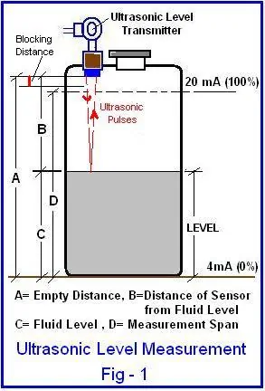
An ultrasonic level sensor emits a short burst of high-frequency sound (typically 20–200 kHz) from a piezoelectric transducer mounted at the top of a tank. The sound pulse travels through air, hits the liquid surface, and bounces back. The sensor measures the round-trip time and calculates distance using a simple formula:

Distance = (Speed of Sound × Time) ÷ 2

The speed of sound in air is roughly 343 m/s at 20°C. Since this speed changes with temperature—about 0.17% per °C—every practical ultrasonic sensor includes a built-in temperature compensation circuit. Without it, a 30°C temperature swing can introduce 1.5% measurement error.

Ultrasonic level sensor measurement diagram: the sensor calculates level from the echo transit time.

The sensor’s microprocessor filters out false echoes from tank internals—pipe fittings, agitator blades, weld seams—using echo suppression algorithms. This is called “false echo mapping” and is configured during commissioning.

What Are the Types of Ultrasonic Level Sensors?

Ultrasonic level sensors fall into two main categories based on output type and measurement method.

By output:

  • Continuous level transmitters — Output a 4–20 mA or digital signal proportional to the level. Used for process monitoring and control.
  • Point level switches — Trigger an alarm or relay at a preset level. Used for overfill protection or low-level alarms.

By mounting:

  • Top-mount (non-contact) — Sensor sits above the liquid. Most common type. Measures through air gap.
  • External clamp-on — Mounts on the outside of the tank wall. Sound travels through the tank material. No process penetration needed. Works on metal and plastic tanks up to 30 mm wall thickness.
TypeRangeAccuracyBest For
Compact transmitter (2-wire)0.3–8 m±3 mmSmall tanks, water treatment
Standard transmitter (4-wire)0.5–15 m±3 mmChemical tanks, open channels
Long-range transmitter1–30 m±5 mmLarge storage tanks, silos
Clamp-on (external)0.1–5 m±5 mmSealed tanks, hazardous media

Ultrasonic vs Radar Level Sensor: Which One Should You Use?

Ultrasonic sensors use sound waves. Radar sensors use electromagnetic waves. That single difference drives all the practical trade-offs.

FactorUltrasonicRadar (non-contact)
Affected by temperatureYes — needs compensationNo
Affected by vapor/foamYes — can lose echoMinimal
Works in vacuumNo — needs air to propagateYes
Max range~30 m~70 m
CostLower ($200–$800)Higher ($500–$3000)
Best applicationWater, wastewater, chemicalsHigh-temp, high-pressure, volatile

Use ultrasonic when the application is straightforward: open tanks, water and wastewater, non-foaming chemicals, and ambient conditions below 80°C. Switch to radar level sensors when you have heavy foam, vapor blankets, high temperature, vacuum, or tanks deeper than 20 m.

What Applications Are Ultrasonic Level Sensors Best For?

Ultrasonic level sensors handle most ambient-condition liquid applications well. Here are the areas where they are the default choice in the field.

Water and Wastewater Treatment

Wastewater plants use ultrasonic sensors in equalization tanks, wet wells, clarifiers, and sludge holding tanks. The non-contact design means no fouling from grease, sludge, or chemical dosing agents. Most municipal plants standardize on ultrasonic for open-top tanks. For more on water tank level sensors, see our selection guide.

Chemical Storage Tanks

Acids, caustic solutions, and solvents corrode contact-type sensors within months. An ultrasonic sensor mounted above the liquid avoids all media contact. Common media include sulfuric acid, sodium hydroxide, hydrochloric acid, and various organic solvents.

Open Channel Flow

Paired with a Parshall flume or V-notch weir, an ultrasonic sensor measures the head (water height) to calculate flow rate. This is a standard setup in irrigation canals, stormwater outfalls, and treatment plant influent channels.

Bulk Solids and Powder

Grain bins, cement silos, and aggregate hoppers use ultrasonic sensors for inventory management. The key: use a sensor rated for twice the actual distance. Dust and irregular surfaces weaken the echo, so the extra power margin ensures a clean return signal. Mount the sensor perpendicular to the material’s angle of repose.

How to Install an Ultrasonic Level Sensor Correctly

Installation errors cause more ultrasonic sensor failures than product defects. Follow these five rules.

  1. Respect the dead zone (blocking distance). Every sensor has a minimum distance (typically 15–50 cm) below the transducer face where it cannot measure. Make sure the maximum liquid level never enters this dead zone.
  2. Mount perpendicular to the liquid surface. Even a 3° tilt sends the echo away from the sensor. Use a level to verify the mounting angle.
  3. Keep away from fill streams. Mount the sensor at least 30 cm from the inlet pipe. Turbulence, splashing, and foam near the fill point cause false echoes.
  4. Avoid obstructions in the beam path. The ultrasonic beam spreads at roughly 5–12° depending on frequency. Ladders, baffles, and heating coils within the beam cone will generate interference. For guidance on stilling well installations, refer to our design guide.
  5. Use a sun shade outdoors. Direct sunlight heats the transducer housing and creates a temperature gradient between the sensor and the air path. This introduces measurement drift. A simple sun shade solves the problem.

How to Select the Right Ultrasonic Level Sensor

Choosing the right ultrasonic level sensor comes down to four parameters.

ParameterWhat to CheckTypical Range
Measurement rangeTank height from sensor to lowest level0.3–30 m
Process temperatureAir temperature at sensor face, not media temp-40 to +80°C
Process connectionThread type and size matching your tank nozzleG1½”, G2″, 2″ NPT, DN50 flange
Output signalMatch your PLC/DCS input card4–20 mA, HART, RS485 Modbus

Also check: Is there heavy foam? (Consider guided wave radar instead.) Is the tank under pressure or vacuum? (Ultrasonic will not work — the sound pulse cannot propagate.) Is the atmosphere dusty or full of vapor? (Select a higher-power sensor or switch technology.)

For explosion-hazard areas, specify an ATEX/IECEx certified ultrasonic sensor. Sino-Inst offers Ex d (flameproof) and Ex ia (intrinsically safe) versions. See our Class 1 Div 1 vs Div 2 guide for zone classification details.

Featured Ultrasonic Level Sensors

ULT-100A Level Transducer

TKWL-1600 ultrasonic level transducer for tanks, sumps and open channels. Non-contact, low-maintenance, 4-20mA output — installs in minutes without draining the process.

ULT-200 Level Detector

Portable ultrasonic CO2 bottle / cylinder level indicator. Detects the liquid / gas interface through metal, glass and plastic walls — no opening or weighing needed.

HS-2000 Clamp-On Sensor

Clamp-on ultrasonic flow meter — no pipe cutting, no shutdown, no wetted parts. Standard and high-temperature transducers cover pipes from DN15 up to DN6000.

FAQ

Can an ultrasonic sensor measure level through a closed tank?

A standard top-mount ultrasonic sensor works fine in sealed tanks as long as the tank is not pressurized or under vacuum. For sealed tanks where you cannot install a nozzle, use a clamp-on (external mount) ultrasonic sensor that transmits sound through the tank wall.

What is the maximum temperature for an ultrasonic level sensor?

Most standard ultrasonic sensors operate up to 80°C process temperature. The limiting factor is the air temperature at the transducer face, not the liquid temperature at the bottom of the tank. For higher temperatures, consider a radar level sensor.

Does foam affect ultrasonic level measurement?

Yes. Dense foam absorbs the sound pulse and prevents a clean echo return. Light surface foam (less than 5 cm thick) usually does not cause issues. Heavy or thick foam requires switching to a guided wave radar or contact-type sensor.

How accurate is an ultrasonic level sensor?

Typical accuracy is ±3 mm for ranges up to 10 m. Longer-range models (15–30 m) usually spec ±5 mm. These figures apply under stable conditions. Turbulence, temperature gradients, and vapor can degrade accuracy to ±0.5% of range in worst cases.

Can ultrasonic sensors measure solid levels in silos?

Yes. Ultrasonic sensors measure grain, cement, powder, and aggregate levels. The key is to select a sensor with twice the actual required range. The uneven surface of bulk solids scatters the echo, so the extra power compensates for signal loss. Mount the sensor perpendicular to the material’s angle of repose for best results.

What is the difference between an ultrasonic level sensor and an ultrasonic level transmitter?

Functionally, they are the same device. “Sensor” often refers to the transducer element alone. “Transmitter” refers to the complete instrument with signal processing, display, and a calibrated output (4–20 mA or digital). In practice, most people use both terms interchangeably.

Need help selecting an ultrasonic level sensor for your application? Our instrumentation engineers can review your tank specs and recommend the right model. Contact us for a free consultation and quote.

Request a Quote

Please enable JavaScript in your browser to submit the form

Diesel fuel tank level gauges & Indicators

Updated: April 13, 2026

A diesel fuel tank level gauge measures the amount of fuel remaining in a storage tank or vehicle fuel tank. The right gauge prevents run-dry shutdowns, catches fuel theft early, and keeps inventory records accurate. Choosing the wrong type leads to drift, fouling, or false alarms — all common problems in fuel storage. For sensor-by-application selection on buried tanks, our underground tank level indicator selection by application.

This guide covers the five main types of diesel tank level gauges, where each one works best, and how to set up a monitoring system for industrial tanks and vehicle fleets.

Contents

What Are the Types of Diesel Fuel Tank Level Gauges?

Five sensor technologies cover the majority of diesel fuel level applications. Each has trade-offs in accuracy, cost, and installation complexity.

Magnetostrictive Level Transmitter

A magnetostrictive probe sits vertically inside the tank. A float carrying a magnet rides the probe as the fuel level changes. The electronics measure the float’s position by timing a current pulse along a waveguide wire. Accuracy reaches ±1 mm over ranges up to 6 m. This is the default choice for aboveground diesel storage tanks in refineries, fuel depots, and power plants where high accuracy matters for custody transfer and inventory accounting.

Float Level Gauge (Mechanical)

A float connects to a dial indicator via a cable and pulley. As diesel level rises or falls, the float moves and the dial reads out directly. No power required. Accuracy is ±5–10 mm. Simple, cheap, and reliable for small tanks (under 3 m) where a visual reading is enough. Common on generator day tanks and small bulk storage. For more on float sensors, see our water tank level sensor guide.

Ultrasonic Level Sensor

Mounted on top of the tank, an ultrasonic sensor sends a sound pulse and times the echo. No contact with the diesel. Accuracy is ±3–5 mm for ranges up to 10 m. Works well on open-top or vented tanks. Not suitable for pressurized tanks or tanks with heavy vapor above the fuel surface. For technical details, see our ultrasonic level sensor guide.

Radar Level Sensor

Radar uses electromagnetic waves instead of sound. Unaffected by temperature, vapor, or pressure changes. Accuracy is ±1–3 mm. The best option for large diesel storage tanks (10–30 m), pressurized tanks, and tanks with heavy condensation or diesel vapor. Higher cost than ultrasonic, but more reliable in harsh conditions. See our stilling well design guide for radar installation best practices.

Hydrostatic Pressure Transmitter

A pressure sensor at the bottom of the tank measures the hydrostatic head. Level = Pressure / (Density × Gravity). Accuracy depends on knowing the diesel density accurately — typically ±5–10 mm after density compensation. Good for underground tanks where top-mount access is limited. Submersible versions are rated IP68 and handle buried fuel tanks well.

How Do They Compare? Selection Table

TypeAccuracyRangePowerCostBest For
Magnetostrictive±1 mm0.1–6 m24 VDC$$$Bulk storage, custody transfer
Float (mechanical)±5–10 mm0.3–3 mNone$Small tanks, generator day tanks
Ultrasonic±3–5 mm0.3–10 m24 VDC$$Vented storage tanks, water treatment
Radar±1–3 mm0.5–30 m24 VDC$$$$Large tanks, pressurized, harsh vapor
Hydrostatic±5–10 mm0.5–100 m24 VDC$$Underground tanks, deep wells
Diesel fuel tank level gauge comparison by accuracy, range, and application.

Mechanical vs Electronic: Which Is Better for Diesel Tanks?

Mechanical gauges (float + dial) require no power, no wiring, and no calibration. They work for decades with minimal maintenance. The trade-off: no remote reading, no alarm output, and no data logging. If you only need a local visual check on a small day tank, mechanical is hard to beat.

Electronic gauges (magnetostrictive, ultrasonic, radar, hydrostatic) provide a 4–20 mA or RS485 output that connects to a PLC, SCADA system, or cloud-based monitoring platform. They support high/low alarms, trend logging, and remote access. For any tank where fuel management, theft detection, or regulatory reporting is required, electronic is the only practical option.

Most industrial diesel installations use electronic gauges on the main storage tanks and mechanical gauges on small auxiliary tanks (generator sets, pump skids) where remote monitoring isn’t justified.

How to Set Up a Diesel Tank Level Monitoring System

A complete monitoring system has three layers: sensor, data acquisition, and display/alarm.

  1. Sensor layer. Install a level transmitter on each tank. Magnetostrictive for high-accuracy inventory. Ultrasonic or hydrostatic for general monitoring. Output: 4–20 mA or RS485 Modbus RTU.
  2. Data acquisition layer. A PLC, RTU, or IoT gateway collects signals from all sensors. For remote sites (fuel depots, cell towers, pipeline pump stations), a 4G/LTE cellular gateway transmits data to a cloud server. For on-site systems, wire the 4–20 mA signals directly to the plant DCS or SCADA.
  3. Display and alarm layer. The SCADA or cloud dashboard shows real-time levels, consumption trends, and fill history. Configure high-level alarms (overfill protection), low-level alarms (run-dry prevention), and abnormal consumption alerts (theft detection). Most systems log data at 1–5 minute intervals.

For tank farms with 5+ tanks, add a temperature transmitter to each tank. Diesel volume changes ~0.08% per °C. Without temperature compensation, a 30°C seasonal swing introduces ~2.4% volume error — significant for custody transfer and tax reporting.

How Do You Monitor Fuel Level in a Vehicle Fleet?

Fleet fuel monitoring uses a different approach. Vehicle tanks are small (100–500 L), move constantly, and have no fixed wiring.

The standard solution is an external clamp-on ultrasonic sensor mounted under the fuel tank. It transmits sound through the tank bottom and measures the diesel level without any drilling or tank modification. The sensor connects to a GPS tracker that reports level data via cellular network to a fleet management platform.

This setup detects fuel theft (sudden level drops), unauthorized refueling, and abnormal consumption patterns. Typical accuracy is ±5 mm, which translates to ±2–5 L depending on tank geometry. The sensor draws under 100 mA and runs off the vehicle’s 12/24 V power.

What Are Common Installation Mistakes?

Four mistakes account for most diesel tank gauge failures in the field.

  1. Wrong probe length. Magnetostrictive probes must be cut to match the tank depth. Too short and you miss the bottom 10–20 cm of fuel. Too long and the float bottoms out before the tank is empty. Measure the actual tank depth from the nozzle flange to the tank floor.
  2. Ignoring diesel density variation. Hydrostatic gauges calculate level from pressure. If the density setting is wrong (for example, using water density instead of diesel at 0.84 kg/L), the level reading will be off by 16%. Always set the density parameter to match your actual diesel grade.
  3. Mounting ultrasonic sensors on pressurized tanks. Sound waves need air to propagate. A nitrogen-blanketed or pressure-rated diesel tank will give no echo return with an ultrasonic sensor. Use radar or magnetostrictive instead. For more on pressure transmitter selection, see our technical guide.
  4. No lightning protection on outdoor tanks. Electronic level transmitters on outdoor diesel tanks are exposed to lightning. Install surge protectors on all signal cables. A single lightning event can destroy every transmitter on a tank farm.

Featured Diesel Tank Level Gauges

LD Magnetostrictive Transmitter

Magnetostrictive level transmitter with ±1 mm resolution for high-accuracy tank gauging. Preferred choice on fuel depots, API terminals and chemical inventory measurement.

LR Flange-Mount Level Sensor

Magnetostrictive level transmitter with ±1 mm resolution for high-accuracy tank gauging. Preferred choice on fuel depots, API terminals and chemical inventory measurement.

LT Digital Display Level Sensor

Magnetostrictive level transmitter with ±1 mm resolution for high-accuracy tank gauging. Preferred choice on fuel depots, API terminals and chemical inventory measurement.

FAQ

How do you measure diesel fuel level in an underground tank?

Submersible hydrostatic pressure transmitters are the standard for underground diesel tanks. The sensor is lowered to the tank bottom and measures the hydrostatic pressure of the diesel column above it. Set the density parameter to 0.82–0.86 kg/L depending on your diesel grade. Magnetostrictive probes also work if you have top access through a fill riser.

What accuracy do I need for diesel fuel inventory?

For custody transfer and tax reporting, you need ±1 mm accuracy — magnetostrictive or radar. For operational monitoring (refill scheduling, low-level alarms), ±5 mm is sufficient — ultrasonic or hydrostatic. For vehicle fleet fuel theft detection, ±5 mm (external ultrasonic) is practical and cost-effective.

Can I use a float gauge on a diesel storage tank?

Yes, for tanks under 3 m depth where you only need a local visual reading. Float gauges are reliable for generator day tanks (500–5000 L). For anything requiring remote monitoring, alarms, or data logging, switch to an electronic gauge with a 4–20 mA or digital output.

Do diesel tank level gauges need explosion-proof certification?

Yes, if the tank is in a classified hazardous area. Diesel vapor forms an explosive atmosphere above the liquid surface. Most diesel storage areas are classified as Class I, Division 1 or 2 (NEC) or Zone 1/Zone 2 (IECEx). The level gauge must carry the appropriate Ex rating. Sino-Inst offers ATEX and IECEx certified models. See our Class 1 Division 1 vs Division 2 guide for details.

How do you detect fuel theft from a diesel tank?

Set up a monitoring system that logs level at 1-minute intervals. Configure an alarm for any level drop exceeding a threshold (for example, 5 L in 10 minutes) when no scheduled dispensing is active. A sudden drop outside of normal consumption or refueling patterns triggers an alert. Combine with GPS data for vehicle fleets to correlate location with fuel events.

What is the typical lifespan of a diesel tank level gauge?

Magnetostrictive and ultrasonic gauges typically last 10–15 years with minimal maintenance. Float gauges can last 20+ years since they have no electronics. Hydrostatic sensors may need membrane replacement every 5–8 years depending on diesel quality and water contamination levels.

Need help selecting the right level gauge for your diesel tank? Our engineers specialize in fuel storage measurement. Contact us with your tank dimensions, diesel type, and monitoring requirements for a free recommendation.

Request a Quote

Please enable JavaScript in your browser to submit the form

Quickly Set Level Monitoring System for Industrial Holding Tanks

Holding tank level indicators can help us monitor and control liquid levels. Whether it is a fuel tank on a truck, a fire water storage tank, an underground sewage storage tank, or even a marine storage tank, etc. Replacing manual inspection with automated Level Monitoring System can be faster and more accurate.

Disassemble the system

Before setting up a Level Monitoring System for Industrial Holding Tanks, we need to first understand what should be included in the system.
Based on our many years of experience in level monitoring services at Sino-Inst, we have simplified the entire system from complexity. Simply put, the system can be divided into two parts: Level sensor + Tank level Monitor.

These two parts are both independent and interrelated. You can choose different types of level sensors and Tank level Monitors according to actual needs. Then use the connection key, which is our signal output (such as RS485, 4-20mA) to make them work synchronously.

Exploring Advanced Level Monitoring Technologies

Part 1: Level Sensor

We have analyzed the working principles, advantages and disadvantages of various level sensors in detail in our previous blog. You can learn more about it. Here, we briefly introduce a few commonly used ones:

  • External ultrasonic level sensor: It can be simply pasted on the bottom of the tank for liquid level measurement. Suitable for tanks less than 2 meters. Like a truck fuel tank.
  • Capacitive level sensor: suitable for liquid level measurement under various special conditions such as high pressure, high temperature, extremely low temperature, etc.
  • Ultrasonic level sensor: low-cost non-contact measurement. You can choose anti-corrosion and explosion-proof materials.
  • Radar level sensor: wider application range. High measurement accuracy. Can be applied to tanks with a measuring range of 30m.
  • Magnetostrictive level sensor: the most accurate level sensor. Can be customized as an oil level interface sensor. It can also be customized to measure temperature at the same time.
  • Hydrostatic pressure level sensor: enables low-cost, large-range measurement.
  • Float level sensor: The measurement principle is the simplest.

Part 2: Monitor System

We generally configure paperless liquid level recorders for users to measure and record on-site liquid level signals. It can even perform alarm, signal output, printing and other functions according to user needs.

For example, some of our common models:

7620/7620R Series LCD Volume Display Regulator/ Recorder is specifically designed for industrial on-site regular and irregular canned liquid, volume and mass conversion.

The device has empowered by the surface mounting technology, featuring the design of multiple-layered protection and isolation, with a strong anti-interference capability and high reliability. It has used the embedded operating system with USB data dump function. The data storage time could reach up to 720 days. By using U disk and host computer analysis software, one could call and view the historic curve of process variants and relevant historic data from time to time. It also could match with various liquid sensors, such as ultrasonic liquid level meter. The device has sound anti-theft and anti-damage and other features.

T710 series paperless recorder adopts the new large-scale integrated circuits to realize the reliable protection and robust anti-jamming for input, output, power supply and signals. The recorder can achieve eight-channel universal signal input (the configurable and optional inputs include standard voltage, standard current, thermocouple, thermal resistance and millivolt), four-channel alarm output and one feed output. It has the RS485 communication port, Ethernet port, micro-printer port, USB device port and SD card socket. The recorder enjoys a Powerful display function, which can achieve real-time graphic display, historical graphic recalling, bar graph display and alarm status display.

Universal input of NHR-8100/8700 series color paperless recorder (capable of inputting by means of configuration: standard voltage, standard current, thermocouple, thermal resistance, millivolt, etc.). It can be equipped with 18-channel alarm output or 12 -channel analog transmitting output, RS232/485 communication interface, Ethernet interface, mini-printer interface, USB interface and SD card socket; can provide sensor distribution; is equipped with powerful display function, real-time curve display, historical curve retrospection, bar graph display, alarm list display, etc. The meter is of high cost effectiveness due to its humanized design, perfect function, reliable hardware quality and exquisite craftsmanship.

Other requirements support customization.

Part 3: Featured Products

Steps to quickly build an industrial holding tank level indicator

Let’s say you only have the tank now. There is no liquid level sensor or system.

Understand the basic parameters of the tank. For example, the shape, height, width, wall thickness, pressure, and temperature of the tank. Is there stirring inside the tank?

  • Understand the condition of the media. Is the medium corrosive? Will there be evaporation?
  • Be clear about your needs. For example: You want to achieve synchronous detection of liquid levels in 6 storage tanks.
  • Choose appropriate level sensors and tank level monitors. Make purchases based on the parameters and needs you have mastered above.
  • Install the liquid level sensor. (For specific installation steps and installation details, refer to the manufacturer’s recommendations)
  • Signal connection. Output the signal line of the level sensor to the Tank level Monitor system. For example, the access of 4-20mA signal line.
  • Calibration and testing. After setup and testing, you can easily monitor the liquid level of industrial holding tanks.

If you already have a holding tank level sensor, just select the applicable level monitors based on the output signals supported by the level sensor.

More Level Measurement Solutions

We at Sino-Inst are professional suppliers of holding tank level indicators. Our level sensors and level monitoring systems are widely used in various industries. For example, it can be used as sewage holding tank level indicator or marine holding tank level indicator.

In addition to supplying holding tank level indicators for tanks, we also provide pressure and temperature measurement solutions for various tanks. Including measurements under extreme conditions such as explosion-proof, anti-corrosion, high temperature, extremely low temperature, etc. There are also flow meters that can be used to monitor the flow of tank media filling pipes.

If you need to configure holding tank level indicators or other holding tank detection instruments, please feel free to contact our sales engineers!

Request a Quote

Please enable JavaScript in your browser to submit the form

Enhancing Marine Tank Monitoring with Advanced Marine Water Tank Level Sensors

Marine Water Tank Level Sensors have always been an important part of the marine tank monitoring system. There are many places on ships where water levels need to be detected. Such as fuel, fresh water and sewage storage tanks. The liquids in these tanks are a critical resource for ship operations and require constant monitoring to ensure supply and appropriate storage. For example, the water level in the water storage tanks and pipelines of the fire protection system also needs to be monitored to ensure that there is sufficient water supply in an emergency. Even equipment that handles seawater, sewage or other waste liquids needs to monitor water levels to ensure proper operation of the equipment.

What are Marine Water Tank Level Sensors?

Marine Water Tank Level Sensors are specially designed to measure the water level inside ships. For example, in fresh and drinking water as well as gray water or waste water storage tanks on ships, Marine Water Tank Level Sensors can detect liquid levels from very low to very high.

Marine Water Tank Level Sensors generally use capacitive, hydrostatic, or radar measurement technologies. Convert the water level into an analog signal and then transmit it to the marine tank monitoring system. To effectively monitor, record and control the liquid level in the tank. And the sensors are often used in conjunction with alarm systems to alert users when the level in the tank reaches a certain level.

marine tank monitoring system

Marine Tank Monitoring System is a system used on ships to monitor the liquid levels of various storage tanks (such as oil, fresh water, sewage, etc.) in real time. It is an important part of ensuring the safe and efficient operation of ships.

In addition to monitoring water levels, other liquid levels also need to be monitored on ships. The installation of liquid level measurement and alarm systems on oil tankers and chemical ships is to monitor cargo tanks and other oil and water tanks. On the one hand, by measuring the liquid level, the crew can keep track of the various conditions of the ship during navigation to ensure the best loading of the ship. More importantly, it is to prevent the liquid level from being too high and causing overflow. To avoid causing fires and contaminating the surrounding marine environment.

The following are some basic features and components of the system:

  • Function:
    • Monitor the liquid level in the storage tank in real time.
    • Record and analyze liquid level data.
    • Sounds an alarm when the liquid level exceeds the preset range.
    • Sometimes other parameters such as temperature and pressure of the storage tank can also be monitored.
  • Sensor:
    • The liquid level sensor is the core component and can be float type, capacitive type, radar type, pressure type, etc.
    • As needed, it may also include temperature sensors, pressure sensors, etc.
  • Display and control terminal:
    • Usually located in the control room or bridge of the ship, it is used to display the liquid level information of each storage tank in real time.
    • Allows operators to set alarm thresholds, view historical data, and more.
  • Correspondence:
    • Communication is required between the sensors and control terminals within the system, which may be wired (such as RS485, Ethernet) or wireless.
    • In more advanced systems, remote monitoring capabilities may also be provided, allowing a land-based management center or other vessel to obtain data in real time.
  • Data processing and storage:
    • Systems will typically include a data processing unit to receive, process and store data collected from sensors.
    • Facilitate subsequent analysis, statistics and reporting.
  • Power and backup:
    • Considering the particularity of ship power supply, the system usually has its own power module with battery backup to ensure that it can still work normally in the event of a short-term power interruption.
  • Alarm function:
    • When the liquid level exceeds the preset safety range, the system will automatically send out an audible and visual alarm to remind the operator to handle it in time.

Marine Water Tank Level Sensors is important for better tank monitor

Through the above introduction, you should have understood that Marine Water Tank Level Sensors are important for better tank monitor.

Equipment for monitoring the level of liquids in ship water tanks (such as fresh water, sewage, drinking water, etc.). These sensors play a vital role in the operation and management of ships.

For example, the simplest thing is to ensure the safety of ships.

Sudden changes in tank level can be a sign of a leak or other malfunction on your vessel. Through real-time monitoring, potential problems can be discovered and dealt with in time to prevent accidents.

OK So if we want to configure Water Tank Level Sensors for our or our customers’ ships, which one should we choose? What types of Marine Water Tank Level Sensors are there?

Types of Marine Tank Level Sensors

Based on our many years of experience in liquid level measurement services at Sino-Inst, the level sensors commonly used for ship liquid level monitoring are as follows:

When the liquid level rises or falls, the float also rises or falls. Through the movement of the float on the vertical guide rod, the liquid level information can be output into an electrical signal.

  • Advantages: simple structure, low cost and high reliability.
  • Disadvantages: It may be interfered by sediments or viscous liquids, and is not suitable for use in high-temperature or high-pressure liquids.

The sensor is submerged in the liquid and measures the liquid level based on the water pressure generated by the liquid column. The higher the liquid height, the greater the water pressure.

  • Advantages: High accuracy, not affected by liquid properties (such as color, transparency), suitable for deep water storage tanks.
  • Disadvantages: Requires regular calibration and maintenance, may be affected by high temperatures and corrosive liquids.

The sensor acts as a part of a capacitor, and changes in the liquid level will cause changes in the capacitance value, thereby measuring the liquid level.

  • Advantages: Fast response and can be used with many types of liquids, including corrosive and viscous liquids.
  • Disadvantages: May be affected by sediment or other impurities and require periodic cleaning and calibration.

The sensor emits microwave or millimeter wave signals that are reflected back by the liquid surface. The liquid level height is calculated based on the time difference between the transmitted and received signals.

  • Advantages: High accuracy, not affected by liquid properties or sediments. Contactless design reduces maintenance requirements.
  • Disadvantages: Relatively high cost, installation and calibration may be complicated.

How to Choose Level Sensors for Marine Tanks?

Choosing a suitable marine liquid level meter requires comprehensive consideration based on practical applications and various factors to ensure that it can not only meet the measurement needs, but also have high cost performance and reliability.

Here are a few points to consider based on our experience:

  • Liquid properties:
    • Corrosiveness: For highly corrosive liquids, corrosion-resistant materials and sensor types need to be selected.
    • Viscosity: Some sensors may be interfered by highly viscous liquids or sediments.
    • Temperature and Pressure: The operating temperature and pressure of the liquid may place specific requirements on sensor materials and design.
  • Measuring range: The measuring range of the liquid level gauge needs to be clarified to ensure that it is suitable for the depth of the tank or the variation range of the liquid level.
  • Tank shape and installation location: The shape of the tank and installation space may limit the type of level sensor. For example, the tank may only have an external level sensor option.
  • Accuracy requirements: Determine the required measurement accuracy based on the requirements of the actual application.
  • Installation and maintenance:
    • Ease of installation: Some level gauges may require special tools or expertise to install.
    • Maintenance needs: Consider whether the sensor is easy to clean, calibrate, or replace.
  • Output and communication: Select the appropriate output interface (such as 4-20mA, RS485, Modbus, etc.) according to the ship’s monitoring system or other equipment.
  • Power requirements: Consider whether the ship’s power supply and the level gauge’s power requirements match.
  • Cost: In addition to the cost of the equipment itself, the total cost of installation, maintenance, and replacement should also be considered.
  • Environmental factors: Consider the environment the ship is in, such as whether there is a lot of salt spray, moisture, vibration, etc., and choose a liquid level gauge that can work stably under these conditions.
  • Additional functions: such as whether remote monitoring function is required, whether there is a built-in temperature or pressure sensor, whether there is an alarm function, etc.
  • Suppliers and brands: Choose suppliers or brands with good reputation and good after-sales service.

FAQ

You can use a specially designed liquid level sensor to monitor the liquid level of your water tank in real time.

These sensors are usually installed at the bottom or top of the water tank and connected to a display or monitoring system so that you can visually view the water level.

Read more about:

Water Tank Level Sensors for Level Control

Water Level Monitoring Sensor/System for Sewage-Wastewater

The Secret of Water Level Control

Tank level sensors determine the height of a liquid by measuring the pressure the liquid exerts on it, changes in capacitance, or by sending and receiving reflected signals such as radar or ultrasonic waves.

When the height of the liquid changes, the signal generated by the sensor changes, and these changes are converted into electrical signals and displayed as the liquid level.

More about: 7 Type Tank Level Senors For Liquid and Solid

There are many sensors used to maintain the water tank level, including float level sensors, submersible hydraulic level sensors, capacitive level sensors and radar level sensors. Which sensor you choose depends on your specific needs and the characteristics of your tank.

A liquid level sensor for water tanks is a device used to detect and measure the water level in a water storage container or tank in real time. It can be several types of sensors that work on different principles, such as those mentioned above.

A tank level monitoring system is an integrated system for real-time monitoring and recording of liquid levels in a storage tank or water tank. The system typically includes one or more level sensors, a central processing unit, display and possibly alarm equipment. When the liquid level exceeds the preset range, the system can automatically trigger an alarm or take other measures.

How to install the Marine Water Tank Sensor?

Installing a marine water tank sensor is a relatively specialized process that requires accuracy and safety. Here’s a basic guide we’ve put together with the installation steps:

  • Choose a suitable location: Choose a location close to the center of the water tank for easy later maintenance.
  • Cleaning and pre-treatment: Remove impurities and ensure the tank level is below the predetermined level if drilling is required.
  • Drilling and fixing: Drill holes and fix the sensor according to the sensor specifications to ensure a seal.
  • Connect the wires to the output: Connect the sensor output wire to the display and make sure the connection is waterproof.
  • Debugging and calibration: Turn on the power and calibrate the sensor according to the guide.
  • Safety and Protection: Provides protection for sensors and ensures wires are securely fastened.
  • Regular inspection and maintenance: Check sensor operation and clean or calibrate as needed.

Installing marine water tank sensors requires meticulous work and specialized knowledge. If you’re not sure how to proceed, it’s best to ask a professional or follow the manufacturer’s installation guide.

More Level Measurement Solutions

We, Sino-inst, are professional tank level gauge manufacturers and suppliers. We have been supplying various types of level sensors for a long time. Including: ultrasonic level meter, radar level meter, hydrostatic level meter, capacitive level sensor, differential pressure level transmitter, etc.

The Marine Water Tank Level Sensors we supply are widely exported to various countries, including the United States, the United Kingdom, Turkey, South Africa, Nigeria, Singapore, and many other countries.

If you have any technical questions about the purchase and installation of Marine Water Tank Level Sensors, please feel free to contact our sales engineers. We will provide you with customized solutions.

Request a Quote

Please enable JavaScript in your browser to submit the form