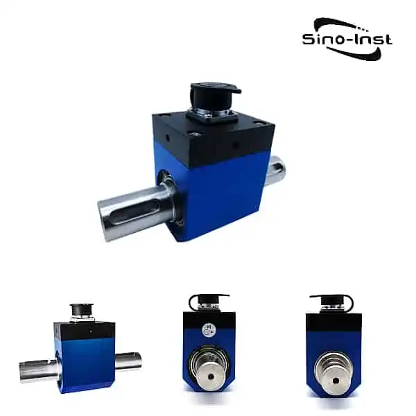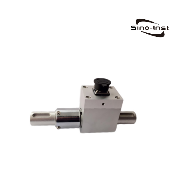
1050C Dynamic Micro Torque Sensor-10 Nm

The 1050C Dynamic Micro Torque Sensor is suitable for low to mid-range torque measurements. Measurable measuring 0.1/0.2/0.5/1/2/3/5/10 Nm. The maximum speed does not exceed 4000 rpm.

Features of 1050C Dynamic Micro Torque Sensor

  • Based on the principle of resistance strain type, power supply and signal output are realized through brushes.
  • Low to medium range torque measurement. It can measure the torque value in both forward and reverse directions.
  • Both ends are connected by shaft keys, which is easy to install and use.
  • The maximum speed does not exceed 4000 rpm.

Technical Parameters

Measuring range1050C   0~0.1/0.2/0.5/1/2/3/5/10 Nm   Nm
Output Sensitivity1.0~2.0mV/V
Straightness L±0.1; ±0.3; ±0.5%F.S
hysteresis H±0.1; ±0.3; ±0.5%F.S
Repeatability R±0.1; ±0.3; ±0.5%F.S
Operating temperature-10~+60
Temperature compensation rangeroom temperature~+60
Zero temperature effect±0.1%F.S/10 ℃
Excitation voltage12VDC
Insulation resistance2000MΩ/100VDC
Input resistance700±10/350±10Ω
Output resistance700±5/350±5Ω
Zero output0~±1%F.S
Safe overload rate120%F.S
Factory standard wire length3m

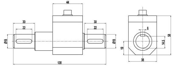
Dimensions

https://www.drurylandetheatre.com/wp-content/uploads/2022/10/1050C-Dynamic-Micro-Torque-Sensor-10-Nm-e1678687084955

Electrical Connection

Connection methodPlug socket numberwire color
Input (power) positive terminal1red
Positive end of output signal2yellow
Negative terminal of output signal3White
Input (power) negative terminal4green
If the plug socket size and wire color change color, please refer to the sensor verification certificate.

Frequently asked questions

Dynamic torque sensor can be divided into contact measurement and non-contact measurement according to the signal transmission mode, both of which should overcome the problem of rotating strands.

In the dynamic measurement process, the measuring element needs to lead the signal line from the rotating shaft to the control circuit of the fixed housing for signal processing.

If it is led out by the collector ring and the carbon brush (similar to the motor brush), it is a contact type;
If the principle of electric, magnetic and optical sensing is adopted, the signal signal is directly transmitted instead of the collector ring and the carbon brush, that is, non-contact measurement.

According to material mechanics, when a torque is applied to a shaft, it will cause a torque deformation. It consists of two physical quantities, one is the torsion angle and the other is the maximum shear stress or strain.

As long as one of them is measured, the torque of the shafting can be obtained according to the relevant calculation formula. Therefore, according to this measurement principle, it can be divided into torsion angle measurement and strain measurement.

Principle of strain measurement.

The most traditional method of strain measurement is to paste resistance strain gauges. With the development of science and technology, in addition to resistance strain gauges, there are many new methods. Such as acoustic surface wave strain measurement, piezoelectric strain measurement and strain measurement by the stretching effect. But the essence of its measurement is to obtain the strain value.

Traditional resistance strain gage torque transducers have strain gages as bridges, glued at 45° and 135° on the elastic axis. When the elastic shaft is torqued, the torsional deformation will lead to the change of bridge resistance, and the change of the strain bridge resistance will be converted into the change of the voltage signal. The signals transmitted from the rotating shaft to the fixed housing mainly include carbon brush contact, electromagnetic induction and wireless transmission.

Read more about: Static / Reaction Torque Vs. Rotary Torque

When the existing torque sensor is used, it is mostly used as a precision torque measurement. After a long time of use, it will cause mechanical fatigue. Therefore, it must be calibrated and tested.

So how to calibrate the torque sensor?

Let’s take a look together!

Torque sensor calibration method and steps:

  1. Calibration preparation: Prepare the calibration tools (weight components, torsion joints (for folding testing machines), enamel discs (for automatic torque machines), rotary testers, torsion handles).
  2. Turn on the industrial control host and open the test software. Make sure that the connection between the pressure sensor and the motion card is stable. The numerical value is within the range of error (0.01gf.cm-0.03gf).
  3. Assemble the auxiliary connectors.
  4. Open the software to select the corresponding range of the sensor. Then open the calibration sensor interface. Clear the value when the sensor has no load.
  5. Select a suitable weight according to the sensor range. Select a small weight for a sensor with a small range, and a larger weight for a large range. For example, choose 200g, 100g weight for 2N.m, choose 500g, 1kg weight for 50N.m. Tie the weight to one end of the connecting piece. Hang it on one end of the pulley through the rope along the groove of the standard piece. Keep the contact state without external force Stablize.
  6. On the software calibration interface, click Allow Calibration. Enter the torque value of the calibration weight (gravity * force arm), and click OK.
  7. Wind the weight in another direction. Check the reverse force value. If the difference is large (>0.5gf.cm), take the average value of the positive and negative force values.
  8. Record the calibration date. Fill in the tool to the “Equipment Sensor Calibration Record Form.
  9. The calibration cycle is normally 1 year. If it is repaired or adjusted during use, it needs to be re-calibrated.

Torque sensors are precision measuring instruments used to measure various torques, revolutions and mechanical thermal efficiencies.

  1. Determine the distance between the prime mover and the load according to the connection form of the shaft and the length of the Dynamic Micro Torque Sensor. Adjust the distance between the prime mover and the load shaft so that the coaxiality of the shaft is less than φ0.03mm. Secure the prime mover and load to the reference plane.
  2. Put the couplings on their respective shafts.
  3. Adjust the distance between the torque sensor and the reference surface. The coaxiality of its axis with the prime mover and the load shaft is less than φ0.03mm. And fix the Dynamic Micro Torque Sensor on the reference surface.
  4. Tighten the coupling and the installation is complete.

If you cannot find an answer to your question in our FAQ, you can always contact us
and we will be with you shortly.

More Featured Torque Sensors

Sino-Inst is a manufacturer of Dynamic Micro Torque Sensors. We offer more than 10 types of Dynamic Torque Transducers. Dynamic Torque Transducers can measure a variety of different mechanical power, rotational speed and torque measuring devices.

Dynamic Micro Torque Sensors are widely used in the following areas:
Application in process industry and process industry;
In sewage treatment systems, measure the relevant power and torque;
Measure the power and torque of machinery such as aircraft, ships, railway locomotives and mines;
Can be used to make viscometers;
Measuring the output power and torque of related devices such as internal combustion engines and rotational forces;
Measure power and torque of torque wrenches, water pumps, etc.

Dynamic Micro Torque Sensor is also called rotary torque transducer, torque transducer. Mainly used for torque measurement in dynamic situations. The dynamic torque sensor is equipped with a speed measuring device, which can measure the rotational speed while measuring the torque. At this time, the torque sensor can also be called a torque speed sensor.

Sino-Inst’s Dynamic Micro Torque Sensor, made in China, have good quality, with better prices. Our Dynamic Micro Torque Sensors are widely used in China, India, Pakistan, USA and other countries.

Sino-Inst’s entire team is well trained, so we can ensure that each customer’s needs are met. If you need any help with your product requirements, whether it is a Dynamic Micro Torque Sensor, level sensors, or other equipment, please give us a call .

Request a Quote

1050C Dynamic Micro Torque Sensor-Micro Torque Measurement 0.1/0.2/0.5/1/2/3/5/10 Nm

The 1050C Dynamic Micro Torque Sensor is suitable for low to mid-range torque measurements. Measurable measuring 0.1/0.2/0.5/1/2/3/5/10 Nm. The maximum speed does not exceed 4000 rpm.

Product SKU: 1050C

Product Brand: Sino-Inst

Product Currency: USD

Price Valid Until: 2029-09-09

Product In-Stock: InStock

Editor's Rating:
5