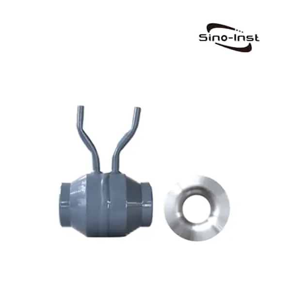
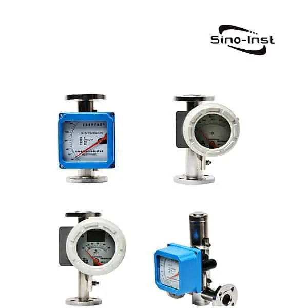
Once the piping system is identified, there are 2 main types of pressure and flow relationships in the piping system: Pressure in the piping system will generally cause an increase in flow, but the exact relationship may vary depending on the major sources of resistance in the system. For many systems where frictional resistance dominates, the relationship between pressure drop and flow is quadratic.
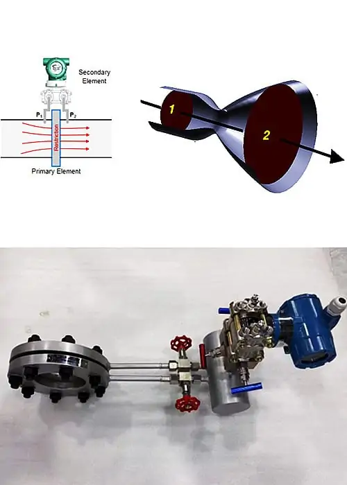
In fluid dynamics, the flow rate and pressure are two fundamental parameters that describe how fluids (like liquids and gases) move through systems like pipes, valves, and pumps.
To understand the relationship between flow and pressure, we need to understand what flow and pressure are, how to work out the flow rate from the differential pressure, and what flow meters are used.
Pressure vs Flow vs Pipe Diameter
What is Pressure?
Pressure: This refers to the force exerted by the fluid per unit area. It is denoted by the symbol P and is typically measured in units like Pascals (Pa), bars, or pounds per square inch (psi).
What is Flow?
Flow: This refers to the volume of fluid that passes through a given surface or point per unit of time. It is often represented by the symbol Q and commonly measured in units such as liters per minute (L/min) or cubic meters per hour (m^3/h).
Flow is also divided into mass flow and volume flow. When the amount of fluid is expressed by volume, it is called volume flow. When the amount of fluid is expressed by mass, it is called mass flow.
Extended reading: Mass Flow Rate vs Volumetric Flow Rate
What is Pipe Diameter?
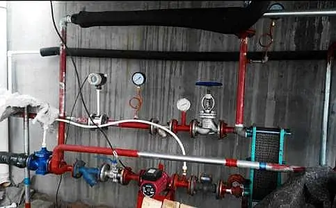
The pipe diameter means that when the pipe wall is relatively thin, the outside diameter of the pipe is almost the same as the inside diameter of the pipe. So the average value of the outside diameter of the pipe and the inside diameter of the pipe is taken as the pipe diameter.
Usually refers to the general synthetic material or metallic pipe. And when the inner diameter is large, the average value of the inner diameter and the outer diameter is taken as the pipe diameter.
Based on the metric system (mm), it is called DN (metric unit).
Does pressure affect flow?
Yes, pressure does affect flow. But this effect is affected by many factors, such as the resistance of the system, the flow pattern, the properties of the fluid, etc. When designing and operating fluid systems, these factors need to be considered to ensure efficient and safe operation of the system.
flow rate and pressure relationship
First of all, flow = flow rate × pipe inner diameter × pipe inner diameter × π÷4. Therefore, the flow and the flow rate basically know one to calculate the other parameter.
But if the pipe diameter D and the pressure P in the pipe are known, can the flow rate be calculated?

The answer is: It is not yet possible to find the flow velocity and flow rate of the fluid in the pipeline.
You imagine that there is a valve at the end of the pipe. When closed, there is pressure P in the tube. The flow rate in the tube is zero.
Therefore: The flow rate in the pipe is not determined by the pressure in the pipe, but by the pressure drop gradient along the pipe. Therefore, it is necessary to indicate the length of the pipeline and the pressure difference between the two ends of the pipeline in order to find the flow rate and flow rate of the pipeline.
Extended Reading: Magnetic Battery Operated Flow Meter
If you look at it from a qualitative analysis point of view. The relationship between pressure and flow in the pipeline is proportional. That is, the greater the pressure, the greater the flow rate. The flow rate is equal to the velocity multiplied by the section.
For any section of the pipeline, the pressure comes from only one end. That is to say, the direction is one-way. When the outlet in the pressure direction is closed (valve closed). The fluid in the tube is prohibited. Once the exit opens. Its flow rate depends on the pressure in the pipeline.
Extended reading: High accuracy pressure transducers
For quantitative analysis, you can use hydraulic model experiments. Install pressure gauges, flow meters, or measure flow-through capacity. For pressure pipe flow, it can also be calculated. The calculation steps are as follows:
- Calculate the specific resistance S of the pipeline. If it is an old cast iron pipe or old steel pipe. The specific resistance of the pipeline can be calculated by Sheverev formula s=0.001736/d^5.3 or s=10.3n2/d^5.33. Or check the relevant form;
- Determine the working head difference H=P/(ρg) at both ends of the pipeline. If there is a horizontal drop h (referring to the beginning of the pipe higher than the end by h).
Then H=P/(ρg)+h
In the formula: H: take m as the unit;
P: is the pressure difference between the two ends of the pipe (not the pressure of a certain section).
P is in Pa; - Calculate the flow rate Q: Q = (H/sL)^(1/2)
- Flow rate V=4Q/(3.1416 * d^2)
- In the formula: Q —— flow rate in m^3/s;
- H —— The head difference between the beginning and the end of the pipeline, in m;
- L —— The length from the beginning to the end of the pipe, in m.
Extended reading: Insertion Ultrasonic Water Flow Meter – Designed for Agricultural Irrigation, Garden Management
Extended reading: High Pressure Flow Meters for Liquids-Steam-Gas
Flow Rate and Pressure Formula
Mention pressure and flow rate. I think many people will think of Bernoulli’s equation.
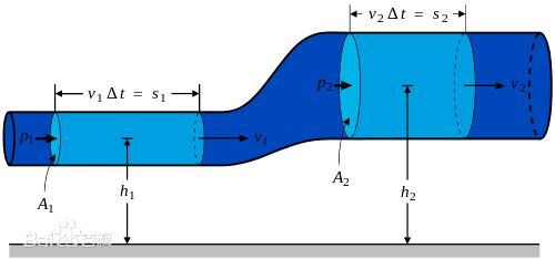
Daniel Bernoulli first proposed in 1726: “In water or air currents, if the velocity is low, the pressure is high. If the velocity is high, the pressure is small”. We call it “Bernoulli’s Principle”.
This is the basic principle of hydraulics before the continuum theory equation of fluid mechanics is established. Its essence is the conservation of fluid mechanical energy. That is: kinetic energy + gravitational potential energy + pressure potential energy = constant.
Extended reading: Fluid flow meter types
Have to be aware of it. Because the Bernoulli equation is derived from the conservation of mechanical energy. Therefore, it is only suitable for ideal fluids with negligible viscosity and incompressible.
Bernoulli’s principle is often expressed as:

This formula is called Bernoulli’s equation.
Where:
- p is the pressure of a certain point in the fluid;
- v is the flow velocity of the fluid at that point;
- ρ is fluid density;
- g is the acceleration of gravity;
- h is the height of the point;
- C is a constant.
It can also be expressed as:

Assumptions:
To use Bernoulli’s law, the following assumptions must be met before it can be used. If the following assumptions are not fully met, the solution sought is also an approximation.
- Steady flow: In a flow system, the nature of the fluid at any point does not change with time.
- Incompressible flow: the density is constant, when the fluid is a gas, the Mach number (Ma)<0.3 is applicable.
- Friction-free flow: The friction effect is negligible, and the viscous effect is neglected.
- Fluid flows along streamlines: fluid elements flow along streamlines. The streamlines do not intersect each other.
Extended reading: Silicon Pressure Sensor
Extended reading: Pressure Sensor Applications-Featured Industry Applications
how to calculate flow rate in pipe?
The flow rate Q can be calculated using the following formula:
Q= A × v
in:
Q is the flow rate, usually expressed in m³/s or L/min.
A is the cross-sectional area of the pipe and can be calculated using the formula π×(d/2)² (for circular pipes), where d is the diameter of the pipe.
v is the average flow velocity of the fluid in the pipe, usually in m/s.
So, to calculate the flow rate in a pipe, you need to know the diameter of the pipe and the velocity of the fluid.
how to calculate flow rate from pressure?
Calculating flow directly from pressure is more complicated because the relationship between them is affected by many factors. Such as the size of the pipe, the viscosity of the fluid and the roughness of the pipe. But under some specific conditions, the following formula can be used:
For laminar flow (slow flow rate and smooth fluid flow):
Q=(πd^4△P)/ (128*μ *L)
in:
Q is flow.
d is the diameter of the pipe.
ΔP is the pressure difference across the pipe.
μ is the viscosity of the fluid.
L is the length of the pipe.
For turbulent flows (faster flows and unstable fluid flow), the relationships are more complex and require the use of more complex formulas or empirical curves.
In summary, calculating flow directly from pressure requires consideration of several factors. In practical applications, flow meters are often used to directly measure flow, or software and simulation tools are used to estimate it.
Flow Rate and Pressure Calculator
Our Converter Tools for Pressure and Flow
Tools for converting and calculating pressure values. Help users choose suitable pressure sensors and transmitters!
Converters for conversion and calculation of flow. Or a calculation tool that requires flow measurement to obtain other measurement parameters. Help users choose the right flow sensor and transmitter!
Featured Flow Meters
Extended Reading: Up to 800°C High Temperature Pressure Sensor
Learn more about pressure and flow rate relationship
If you cannot find an answer to your question in our Flow Rate and Pressure, you can always contact us and we will be with you shortly.
More Flow and Pressure Measurement Solutions
Extended reading: Best Price Ceramic Pressure Sensor
Sino-Inst offers over 50 flow meter for flow measurement. About 50% of these are differential pressure flow meters, 40% is the liquid flow sensor, and 20% are Ultrasonic Level Transmitter and mass flow meter.
A wide variety of flow meters options are available to you, such as free samples, paid samples.
Sino-Instrument is a globally recognized supplier and manufacturer of flow measurement instrumentation, located in China.
Request a Quote

Wu Peng, born in 1980, is a highly respected and accomplished male engineer with extensive experience in the field of automation. With over 20 years of industry experience, Wu has made significant contributions to both academia and engineering projects.
Throughout his career, Wu Peng has participated in numerous national and international engineering projects. Some of his most notable projects include the development of an intelligent control system for oil refineries, the design of a cutting-edge distributed control system for petrochemical plants, and the optimization of control algorithms for natural gas pipelines.


