Tuning Fork Density Meter

Tuning fork density meter is also called density analyzer , fork densitometer or density sensor. Tuning fork density meter is a process control instrument for density as the primary control parameter, or an online analysis instrument for other quality control parameters such as solid percentage. Continuous and real-time online measurement of fluid density. The Tuning fork density meter is installed on the pipeline, in an open or closed storage tank, and the density of the detected fluid depends directly on the vibration frequency received by the tuning fork in the medium where the sensor is inserted.

Tuning Fork Density Meter

Features of Tuning Fork Density Meter

  • Tuning fork vibrating density meter, equipped with a microprocessor-based electronic conversion device. Integrates signal processing, calculation and diagnostic functions;
  • In addition to convincing measurement accuracy and reliability, it can directly communicate with PC through the RS485 interface. Under the ADView software environment, users can directly perform online node configuration, fault diagnosis and data recording;
  • While measuring density and temperature, parameters such as basic density, °API, Brix, concentration percentage, mass percentage, volume percentage, and specific gravity can also be calculated;
  • The instrument adopts various chips with high performance, high speed and high reliability. It optimizes signal acquisition, algorithm and mechanical structure. Thereby improving the response speed, function and reliability of the product;
  • The instrument can switch the alarm mode according to the demand;
  • Customized adjustment sensitivity according to material and site requirements;
  • According to the on-site use environment, we can provide products with high protection, explosion-proof, high temperature and high pressure resistance;
  • In addition, there are many options for the power supply mode, connection mode, and liquid-wetted material of the product for users to match;
  • Simple installation, plug and play, maintenance-free. Can measure the density of mixed media containing solids or air bubbles;
  • Built-in PT100 temperature sensor to realize full temperature automatic compensation;
  • The circular arc structure design of the fork body avoids hanging material and has good stability.

Technical Parameters

Measuring range0 – 2.5 g /cc (0 – 2500 kg/m3),0~100.0%
Calibration range0 – 2.5 g /cc (0 – 2500 kg/m3),0~100.0%
measurement accuracy± 0.001 g /cc (± 1 kg/m3) ,±0.5%
repeatability± 0.001 g /cc (± 0.1 kg/m3) ±0.1%
Operating temperature range-50℃ ~ +150℃
working pressure4mpa
Fluid Viscosity Range0 – 2000 cP
Temperature CoefficientLess than 0.1 kg/m3 /°C (±0.5%) after correction
pressure effectnegligible
Built-in temperature sensorDigital sensor, temperature compensation
Wetted material316L, 2205, 2507 Stainless Steel, Ha C, Titanium, PTFE/PFA
Fork CoatingStandard PTFE or PFA
Power supply24VDC, ≥50mA
Analog signal output4-20mA, 0-1000Hz, RS485 Modbus RTU HART
Output accuracy (20℃)± 0.1% of reading or ± 0.05% FS
Output repeatability (-40 ~ +85°C)± 0.05% FS
process connectionDIN 50 PN16 G1.5″ Thread, 3″ Chuck, IDF and RJT Sanitary
degree of protectionIP65
shellaluminum alloy
  • Model: Alcohol Concentration Meter
  • Length: 150mm
  • Measuring range: 0-2.5g/cc(0-100%)
  • Measurement accuracy: 0.002g/cm3 (0.5%)
  • Voltage: DC24V
  • Explosion-proof: Exd IICT6 Gb
  • Electrical interface: M20*1.5
  • Wetted material: 316L, built-in temperature sensor
  • Liquid crystal display: density, concentration, specific gravity, temperature
  • Model: Submersible tuning fork density meter
  • Four-wire system/two-wire system
  • Power supply: DC24V
  • Connection method: DN50PN16
  • Insertion length: 10m
  • Wetted material: 316L stainless steel
  • Output: 2-way 4-20Ma+RS485/MODBUS
  • Electrical interface: M20*1.5
  • Display: Four digits after the decimal point, LCD, remote PLC/DCS
  • Junction box: aluminum alloy
  • Model: Anti-corrosion tuning fork density meter
  • Four-wire system
  • Power supply: DC24V
  • Connection method: DN50PN16
  • Insertion length: 150mm
  • Wetted material: 316L stainless steel lined with PTFE
  • Output: 2 channels 4-20Ma+RS485/MODBUS/HART
  • Electrical interface: M20*1.5
  • Display: four digits after the decimal point, LCD, remote PLC/DCS
  • Junction box: aluminum alloy
  • Model: Threaded tuning fork density meter
  • Four-wire system
  • Power supply: DC24V
  • Connection method: G1-1/2 thread
  • Insertion length: 150mm
  • Wetted material: 316L stainless steel
  • Can be customized (ha C, titanium, 2205, 2507
  • Duplex stainless steel, load)
  • Output: 2 channels 4-20Ma+RS485/MODBUS/HART
  • Electrical interface: M20*1.5
  • Display: Four digits after the decimal point, LCD, remote PLC/DCS
  • Junction box: aluminum alloy
  • Model: Flange standard tuning fork density meter
  • Four-wire system (for measuring lime slurries, mud, etc.)
  • Power supply: DC24V
  • Connection method: DN50PN16-20592
  • Insertion length: 150mm
  • Wetted material: 316L stainless steel
  • Can be customized (ha C, titanium, 2205, 2507
  • duplex stainless steel, aluminum, PTFE/PFA)
  • Output: 2 channels 4-20Ma+RS485/MODBUS/HART
  • Electrical interface: M20*1.5
  • Display: Four digits after the decimal point, LCD, remote PLC/DCS
  • Junction box: aluminum alloy
  • Built-in temperature sensor, automatic compensation
  • Model: Sanitary Chuck type tuning fork density meter
  • Four-wire system
  • Power supply: DC24V
  • Connection method: 3 inch chuck
  • Insertion length: 150mm
  • Wetted material: 316L stainless steel
  • Can be customized (ha C, titanium, 2205, 2507
  • duplex stainless steel, tan, PTFE/PFA)
  • Output: 2 channels 4-20Ma+RS485/MODBUS/HART
  • Electrical interface: M20*1.5
  • Display: Four digits after the decimal point, LCD, remote PLC/DCS
  • Junction box: aluminum alloy
  • Built-in temperature sensor, automatic compensation
  • Model: Top Mounted Rod Tuning Fork Density Meter
  • Four-wire system/two-wire system
  • Power supply: DC24V
  • Connection method: DN50PN16
  • Insertion length: 3m (shield type)
  • Wetted material: 316L stainless steel
  • Output: 2 channels 4-20Ma+RS485/MODBUS/HART
  • Electrical interface: M20*1.5
  • Display: density, concentration, temperature, remote PLC/DCS
  • Junction box: aluminum alloy
  • Built-in temperature sensor, automatic compensation
  • Model: Pool tank or special type with stirring tank
  • Four-wire system
  • Power supply: DC24V
  • Connection method: DN50PN16
  • Insertion length: 150mm
  • Wetted material: 316L stainless steel
  • Can be customized (ha C, titanium, 2205, 2507
  • duplex stainless steel, tan, PTFE/PFA)
  • Output: 2 channels 4-20Ma+RS485/MODBUS/HART
  • Electrical interface: M20*1.5
  • Display: four digits after the decimal point, LCD
  • Junction box: aluminum alloy
  • Built-in temperature sensor, automatic compensation

Measuring Barrel

316L tee expansion tube type
UPVC/PTFE tee expansion tube type

fork density meter principle

Tuning fork density meter (concentration meter) can perform density detection online in real time. It can be applied to the process control of products with density as the basic parameter or the quality control with solid percentage or concentration percentage as reference.

Typical industries include petrochemical industry, brewing industry, food industry, pharmaceutical industry and mineral processing (such as clay, carbonate, silicate, etc.). Specifically used in the interface detection in multi-product pipelines in the above industries, the density detection of stirred mixtures, the end point monitoring of reactors, and the interface detection of separators.

Tuning fork density sensors work on the principle of vibration of components, which are part of the tuning fork immersed in the liquid to be measured. The tuning fork part is vibrated by an internal piezoelectric device fixed at the bottom end of the fork body. The oscillation frequency is detected by a secondary piezoelectric device fixed at the other end of the fork. The signal is then amplified by the circuit on top. The density of the liquid is closely related to the vibration frequency when the measured liquid flows. When the density of the measured liquid changes, the vibration frequency of the liquid changes accordingly.

Through the following equation, the density of the measured liquid can be accurately calculated.

D= K0+K1T+K2T2
D = uncalibrated density of the measured medium (kg/m3)
T=vibration frequency (μs).
K0, K1, K2 = constant

During the density detection process, the Tuning fork density meter (concentration meter) can automatically compensate the influence of temperature on the density (D) of the measured medium. Pressure has no significant effect on density.

Read More About: What Is Density Meter? and Types

Tuning Fork Density Meter Application

Tuning fork density meters are suitable for measuring the density of various types of liquids and solid substances.

Its application range is quite wide, including but not limited to the following types of substances:

  • Liquids: water, solutions, alcohols, petroleum, chemicals, liquid metals, etc.
  • Solution: solid or gas dissolved in a solvent, such as salt water, acid-base solution, dissolved matter in an organic solvent, etc.
  • Oil: various types of lubricating oil, mechanical oil, edible oil, etc.
  • Chemicals: various chemicals, solvents, acids and bases, etc. nitric acid, phosphoric acid, acetic acid, chloroacetic acid, potassium hydroxide, sodium chloride, sodium sulfate, ammonium sulfate, ammonium bisulfate, ammonium chloride, carbamide, ferric chloride, ammonia, hydrogen peroxide
  • Fuel: gasoline, diesel, liquefied petroleum gas (LPG), aviation fuel, crude oil, kerosene, silicone oil, etc.
  • Plastics: Different kinds of plastic materials, resins, etc.
  • Metal: liquid metal, alloy, etc.
  • Food and beverages: milk, juice, beer, wine, etc.
  • Organic chemical industry: ethanol, methanol, ethylene, toluene, ethyl acetate, ethylene glycol, thinner water
  • Medicine: pharmaceutical intermediates, solvents, polyvinyl alcohol (PVA), citric acid, lactic acid
  • Semiconductors: high-purity solvents, detergents, isopropanol, butyl acetate
  • Printing and dyeing: sodium hydroxide, sodium carbonate, sodium bicarbonate
  • Equipment: cutting fluid, emulsified oil, cutting oil, lubricating oil, antifreeze
  • Batteries: hydrochloric acid, sulfuric acid

Typical application industries:

  • Chemical measurement;
  • reservoir measurement;
  • Slurry measurement;
  • Medicine tank measurement;
  • Cement measurement;
  • printing and dyeing measurement;
  • Waste acid tower measurement;
  • power plant measurement;

Please note that different models of tuning fork densitometers may have limited range of application. Specific measurement ranges and accuracies may depend on equipment specifications and manufacturer’s instructions. Therefore, before choosing a tuning fork density meter for specific material density measurements. It is best to refer to the technical specifications and instructions for use of the equipment to ensure that it is suitable for the substance of interest.

case study

A customer consulted us and needed to measure the density in the sediment pipe dug out by the dredger.

For dredger applications:

  • Installation size: pipe with a diameter of 30cm
  • Insertion Depth Length: 2”
  • Wetted material: mud sand
  • Need signal output: 4-20ma
  • Pressure: 0-10bar
  • Density (or concentration) range: 0-2000kg/m3

Combined with the user’s measurement parameters, we have configured a density meter for the user:

Tuning Fork Density Meter:

  • A layer of wear-resistant material is added to the 316 sensor
  • Power supply DC24V,
  • Medium: Mud,
  • Pressure: 0-10bar,
  • DN50 flange connection,
  • Insertion depth: 180mm,
  • Material: 316+ wear-resistant coating,
  • Output 4-20mA four-wire system + RS485,
  • Density (or concentration) range: 0-2000kg/m3,
  • Installation size: pipe with a diameter of 30cm,
  • English interface

FAQ

A fork density meter uses a tuning fork-shaped probe that vibrates at its natural frequency. When immersed in a liquid, the frequency changes based on the liquid’s density. By measuring this frequency change, the device can accurately determine the density of the liquid.

Tuning fork density measurement is a method to measure the density of a liquid. It uses a fork-shaped sensor that vibrates at a specific frequency. When this fork is exposed to a liquid, the density of the liquid alters the vibration frequency. This change in frequency is then analyzed to calculate the liquid’s density.

A density meter works by employing different principles like oscillation, buoyancy, or radiation to measure the density of a substance. By observing how the substance interacts with these principles, the meter can calculate the mass per unit volume, providing the density of the material.

A densimeter is used to measure the density of a substance, typically liquids or gases. Density is the mass of the material per unit volume and is a crucial property in various industrial, laboratory, and research applications.

More Measurement Solutions

Density is an important parameter in the industrial production process. Density measurement is a very professional field. Different media have different physical properties. Only by selecting suitable instruments according to different media properties can accurate and reliable measurements be made. Unique performance is brought into play.

Sino-Inst is a manufacturer of tuning fork density meters. Our tuning fork density meters are used in a wide variety of industries. Including, petrochemical industry, brewing industry, food industry, pharmaceutical industry and mineral processing (such as clay, carbonate, silicate, etc.). Different media require different densitometers. You can contact our sales engineers for technical support and quotation for tuning fork density meters.

Request a Quote

Please enable JavaScript in your browser to submit the form

Ultrasonic Level Transmitter Installation Guide

What points should be paid attention to for Ultrasonic level transmitter installation? Ultrasonic level transmitter is a widely used non-contact/non-invasive liquid level meter. Including wastewater storage tanks, fuel storage tanks, wastewater treatment pools, etc. Connect to the display table or various DCS systems through 4~20mA or RS485 (Modbus protocol or other customized protocols). Provide real-time liquid level data for industrial automation.
Let’s take a look at the Ultrasonic level transmitter installation requirements and what the installation principles are.

Ultrasonic level transmitter working principle and frequency range

Ultrasonic level transmitter is a cost-effective liquid level measuring instrument. It is mainly composed of three parts: transducer, electronic module and housing. The transducer is one of the core components, and the working frequency of the transducer is one of the important parameters.

Ultrasonic pulses are emitted by sensors (transducers) during the measurement. The sound waves are reflected by the liquid surface and picked up by the same sensor. Converted into electrical signals by piezoelectric crystals. And the distance between the sensor and the surface of the liquid to be measured is calculated by the time between the emission and reception of the sound wave.

The selection of the operating frequency of the ultrasonic transducer is a very important parameter. It is not only directly related to the frequency characteristics and directional characteristics of the transducer. It also affects important performance indicators such as the transmitting power and transmitting efficiency of the transducer. In general, the working frequency of the ultrasonic level gauge is consistent with the working frequency of the ultrasonic transducer.

Working frequency is an important parameter of ultrasonic liquid level gauge. During the production of each ultrasonic sensor of Sino-Inst, the working frequency and impedance characteristics of the transducer are strictly measured and recorded to ensure product quality.

Featured Ultrasonic Level Transmitters

Principles of Ultrasonic Level Transmitter installation

When you’re installing an Ultrasonic Level Transmitter, in addition to meeting the installation requirements, there are certain principles to consider:

  • The distance from the probe’s emission surface to the low liquid level should be less than the range of the purchased transmitter.
  • The distance from the probe’s emission surface to the high liquid level should be greater than the blind zone of the purchased transmitter.
  • The probe’s emission surface should remain parallel to the liquid surface.
  • The location of the probe’s installation should ideally avoid areas directly below inlets and outlets where the liquid surface experiences significant fluctuations.
  • If the pool or tank wall is not smooth, the transmitter’s installation location should be more than 0.3m away from the wall.
  • If the distance from the probe’s emission surface to the high liquid level is less than the blind zone of the purchased transmitter, an extension tube should be installed. The extension tube should have a diameter greater than 120mm, and a length between 0.35m and 0.50m. It should be installed vertically, have a smooth inner wall, and the opening in the tank should be larger than the extension tube’s inner diameter. Alternatively, the tube can extend to the bottom of the tank and should have a diameter greater than 80mm. Holes should be left at the bottom of the tube to keep the internal liquid level of the extension tube at the same height as inside the tank.

Basic Requirements for Ultrasonic Level Transmitter Installation

Before installing an ultrasonic level transmitter, make sure the instrument model meets the environmental requirements of the site, such as process pressure, process temperature, and chemical properties of the medium. This will ensure normal operation after installation.

Ultrasonic level transmitters have a certain emission angle when transmitting ultrasonic pulses. There should be no obstacles within the radiating area of the emitted ultrasonic beam from the lower edge of the ultrasonic transducer to the surface of the medium being measured. This requires avoiding internal facilities such as ladders, heating equipment, and limit switch brackets during installation.

Moreover, note the following when installing an integrated ultrasonic level transmitter:

  • Because of the sound beam angle, the ultrasonic beam should not intersect with the feed flow. Therefore, do not install the integrated ultrasonic level transmitter above the feed flow to ensure measurement of the medium surface and not the feed flow. Make sure the highest material level does not enter the measurement blind zone during installation.
  • The integrated ultrasonic level transmitter must maintain a certain distance from the tank wall.
  • The installation of the integrated ultrasonic level transmitter should aim to keep the transducer vertical to the liquid surface.
  • When installing the instrument outdoors, sunshade and rain protection measures should be adopted to avoid direct sunlight and reduce measurement errors caused by temperature changes.
  • The integrated ultrasonic level transmitter installed in hazardous areas must comply with national explosion-proof hazardous area installation regulations. In places where explosion-proof requirements are needed, the ultrasonic level transmitter must be grounded.

Other Requirements for Ultrasonic Level Transmitter Installation

  • Installation location: Keep the integrated ultrasonic level transmitter at least 200mm away from the tank wall. For a conical container with a flat tank top, install the instrument at the central position of the container top. This ensures measurement to the bottom of the container. For an arch-shaped tank, install it at 1/2 or 2/3 of the tank top radius. For trenches, take into account the load-bearing capacity of the bracket when installing. The probe emission angle should not exceed the A point boundary. The installation height must be within the range.
  • Moisture proofing: If the instrument is installed outdoors, in a humid indoor environment, or on the top of a refrigeration or heating tank, the environment is humid. Rainwater and condensation can flow down. To prevent moisture, before connecting the cable, please bend the cable and lead it downwards to prevent water or moisture from entering the instrument. Tighten the cable sealing sleeve.
  • Stirring effects: If there is stirring in the tank, the integrated ultrasonic level transmitter should be away from the stirrer to eliminate the false echo effect caused by the stirring blades. If foam is generated due to stirring or waves are turned up, use the guide wave tube installation method.
  • Foam effects: During feeding, stirring, or other treatments in the container, foam can form on the surface of some media, causing the ultrasonic level transmitter signal to attenuate. To avoid measurement errors caused by foam, install the sensor in the guide tube or use a guided wave radar level gauge. The guided wave radar level gauge is not affected by foam and is an ideal choice for this type of application.
  • Airflow effects: If there is a strong airflow or air vortex in the container, or it is installed outdoors and the wind is strong, install the sensor in the guide tube or use a guided wave radar level gauge.

Ultrasonic Level Transmitter Installation method:

In open environments, installation is generally achieved using a bracket, securing the device with the included locknut. Alternatively, you can drill a circular hole with a diameter of 60mm at the desired installation spot on the top of the tank or lid, and place the device in it. Then, tighten the locknut from underneath.

It is crucial to ensure that the face of the transmitter’s probe is parallel to the liquid surface being measured.

As illustrated, the probe of the device emits waves that reflect back upon hitting the liquid level. The probe calculates the time taken from emission to reception of these waves to determine the measured empty distance, H.

Subtracting the measured empty distance H from the installed height TH gives you the current liquid level, L. The transmitter’s range is the distance it can measure, and the installed height TH should be less than this range.

The device’s blind zone is the area near the probe that cannot be measured. The distance between the highest liquid level and the probe should be greater than the blind zone. For instance, if the blind zone is 0.5m, the distance between the highest liquid level and the probe must be more than 0.5m.

For example: If the range is 6 meters, the blind zone is 0.45 meters, the actual maximum measurable liquid level is between 0 to 5.5 meters. The emission of waves from the probe is a diffusion process, meaning it has a directional angle. Pay attention during installation to avoid hitting protrusions on the pool wall or the edge of the channel.

FAQ

To install an ultrasonic level transmitter, first, confirm the suitable spot for the device, either on a bracket or on the top of the tank or lid. Drill a hole if necessary. Place the device and secure it with the included locknut. Ensure the face of the transmitter’s probe is parallel to the liquid surface being measured.

Do not install the sensor where the emitted ultrasonic waves might hit obstacles like ladders, heating devices, or limit switch brackets within the tank.
Do not install the sensor where it might directly intersect with the inflow of material.
Avoid installing in a location where the sensor would be exposed to extreme weather conditions without adequate protection.

The ultrasonic sensor should be mounted in a location where its probe can be parallel to the liquid surface being measured. This is often at the top of the tank or the lid. Ensure that the sensor is at a safe distance from the walls of the container and away from any internal installations like ladders or heating devices.

Ultrasonic sensors can be mounted by placing them in the desired spot, either on a bracket or a drilled hole on the top of the tank or lid. Secure the sensor with the included locknut from underneath. Make sure the sensor’s probe is parallel to the liquid surface being measured for accurate readings.

More Level Measurement Solutions

Radar Liquid Level Sensors

Radar liquid level sensors are special tools that use radio waves to measure how much liquid is in a tank…

Ultrasonic Level Transmitter is a widely used level meter. When installing, pay attention to meet the installation requirements, including the environmental requirements of the site, avoiding the facilities in the tank, ensuring that the highest material level does not enter the measurement blind area, and the requirements of the installation location.

When installing an ultrasonic level gauge, installation principles must also be considered. The emitting surface of the probe should be kept parallel to the liquid surface, and the installation position of the probe should avoid the position where the liquid level fluctuates violently, etc.

Sino-Inst is a professional supplier of Ultrasonic Level Transmitter. Our Ultrasonic Level Transmitter is exported to various countries around the world. If you have any questions about Ultrasonic Level Transmitter Installation, please feel free to contact our Sino-Inst technical engineers.

Request a Quote

Please enable JavaScript in your browser to submit the form

Digital Density Meter

More Detection and Analysis Sloutions

Liquid Level Sensor Probes Types and How to Select

Liquid Level Sensor Probes are an essential part of liquid level transmitters. When purchasing a liquid level meter, we must consider the type of Liquid Level Sensor Probes, such as contact or non-contact. Such as the length of the probe, capacitive probe, float probe rod, etc. Or the working principle of Liquid Level Sensor Probes, such as ultrasonic, radar, hydrostatic pressure, etc. Selecting the right type is crucial, as it ensures accuracy, efficiency, and the reliability of the measurement. Whether in industries like food processing, oil and gas, or water treatment, the right sensor can optimize operations and minimize risks.

What is Liquid Level Sensor Probe?

We can understand that a level meter is composed of a probe and a transmitter. Liquid Level Sensor Probes detect the amount of liquid in a specific space, like a tank or a bottle. They’re vital because they help monitor and control the amount of liquid, making sure there’s not too much or too little. This control keeps systems running smoothly and safely, saving both time and money.

For example, Capacitance sensing probe devices for measuring liquid level and converting it to an electrical signal to send to other instrumentation.

You may also have seen straight rod probes, cable probes, and coaxial probes. Or PTFE non-contact probe. Then, according to our many years of experience, Liquid Level Sensor Probes can be classified from several aspects. That is: working principle and material.

From the material point of view, it is easy to understand. It only needs to be compatible with the measured liquid. For example, to measure sulfuric acid, the probe is generally made of anti-corrosion material, such as PTFE. Therefore, when we select enough level meters, we only need to inform the manufacturer of the compatible materials of the measured medium.

Next, let’s look at different types of Liquid Level Sensor Probes from the working principle.

Types of Liquid Level Sensor Probes

Float Level Sensor Probes

Float Level Sensors are widely used in applications where accurate liquid level measurements are needed. Common scenarios include water tanks, where they help in maintaining the desired water level; fuel systems, to monitor fuel storage; sump pumps, to prevent flooding.

Their simplicity and reliability make them suitable for many liquid monitoring tasks.

Advantages:

  • Simple Design: Easy to install and use.
  • Cost-Effective: Suitable for budget-conscious applications.
  • Reliable: Performs well in various standard applications.
  • It can be made into a multi-float form. For multi-level control.

Disadvantages:

  • Limited Use: Not suitable for turbulent or dirty liquids.
  • Wear and Tear: Moving parts may require regular maintenance.

Capacitive Liquid Level Sensor Probes

Capacitive Liquid Level Sensor Probes work on the principle of detecting changes in electrical capacitance caused by the presence of a liquid. The sensor probe forms one plate of a capacitor, and the liquid acts as a dielectric material. Changes in the level of the liquid alter the capacitance, providing a measure of the liquid’s level.

Typical applications include the food and beverage industry, pharmaceuticals, and chemical processing, where non-contact, versatile liquid level sensing is needed, particularly with non-conductive or high-temperature fluids.

Advantages:

  • Works Well on Dielectric Fluids.
  • Simple Mechanical Construction: Easy to manufacture and install.
  • No Moving Parts: This reduces the need for regular inspection and maintenance, and minimizes wear and tear.
  • High-Temperature Fluid Compatibility: Since no sensitive components make contact with the fluid, it can handle high temperatures.
  • Performance Unaffected in Sealed or Pressurized Vessels: The design ensures stable functioning in different container types.

Disadvantages:

  • Incompatibility with Conductive Fluids: Requires an insulated outer tube for working with conductive liquids.
  • Issues with Thick or Sticky Media: Such substances can coat the probe, creating an insulation layer that causes malfunction or affects performance.
  • Requires Calibration: Proper setup is needed to distinguish between liquid and air.
  • Sensitive to Changes in Media: Changes in the dielectric constant of the fluid can affect readings.
  • Potential Obstruction and Cleanliness Issues: Probe protruding into the liquid might cause blockage, attract fouling, and create hygiene concerns.

Ultrasonic Level Sensor Probes

Ultrasonic Level Sensor Probes function by emitting sound waves at ultrasonic frequencies. These waves bounce off the surface of the liquid and are detected by the sensor. By calculating the time taken for the sound waves to return, the distance to the liquid surface, and hence the level, is determined.

Ultrasonic sensors are commonly used in wastewater treatment, oil and gas industries, and irrigation systems, where non-contact measurement is preferred. Their capability to work with dirty or corrosive liquids makes them valuable in such applications.

Advantages:

  • Non-Contact Measurement: Suitable for corrosive or dirty liquids.
  • High Accuracy: Provides precise readings.
  • Versatile: Works well in various conditions. Such as explosion-proof.

Disadvantages:

  • Sensitive to Foam or Vapor: These factors may affect performance.
  • Measuring distance is limited. Ultrasonic is not suitable for larger measuring ranges.

Radar Level Sensor Probes

Radar Level Sensor Probes operate using radio waves. A radar pulse is transmitted, which reflects off the surface of the liquid and returns to the sensor. By measuring the time it takes for the pulse to travel to the liquid and back, the distance, and therefore the level, is calculated.

Radar sensors are highly accurate and can work in extreme conditions, making them suitable for the chemical industry, large industrial tanks, and marine applications. Their adaptability allows for usage with various liquids, even in challenging environments.

Advantages:

  • Highly Accurate: Offers very precise readings.
  • Extreme Conditions: Functions well in tough environments.
  • Versatile: Suitable for various liquids.

Disadvantages:

  • Complex Setup: May require professional installation.
  • More Expensive: Higher upfront cost.
  • Alignment Needed: Proper positioning is crucial.

Magnetostrictive Level Sensor Probes

Magnetostrictive Level Sensor Probes operate by detecting changes in the magnetic alignment within a sensing element. A current pulse generates a magnetic field, interacting with a magnetic float, causing a torsional strain wave. The time taken for this wave to travel is measured, determining the liquid level.

Known for high precision and robust design, these sensors are typically used in petrochemical industries, pharmaceutical manufacturing, and cryogenic applications. Their ability to function in hazardous environments adds to their appeal in these specialized areas.

Advantages:

  • High Precision: Extremely accurate readings.
  • Robust Design: Suitable for hazardous environments.
  • Reliable: Functions well in various industrial settings.
  • Large range cable probes can be customized.

Disadvantages:

  • More Expensive: Higher cost may limit applications.
  • Magnetic Interference: Susceptible to external magnetic fields.

Hydrostatic Level Sensor Probes

Hydrostatic Level Sensor Probes work by measuring the pressure exerted by the liquid at a specific depth, which corresponds to the liquid’s level. The weight of the liquid creates pressure, which the sensor translates into a level reading.

These probes are often utilized in water treatment facilities, sewage systems, deep wells, and fuel tanks.

Their straightforward principle and reliability make them suitable for environments where liquid density is consistent, and there might be slurry or muddy substances, as they can handle such conditions effectively.

Advantages:

  • Simple and Reliable: Easy to use and offers dependable readings.
  • Works with Muddy Liquids: Suitable for slurry or muddy substances.
  • Low Maintenance: Requires minimal upkeep.

Disadvantages:

  • Pressure-Sensitive: Changes in pressure may affect performance.
  • Regular Cleaning Needed: Thick media may require consistent cleaning.

How to Select the Right Liquid Level Sensor Probe

Selecting the right Liquid Level Sensor Probe is essential for accurate and reliable measurements. Here’s a simple guide to help you choose the best option for your needs:

Understanding Your Needs:

  • Liquid Type: Identify if the liquid is conductive, non-conductive, sticky, or corrosive.
  • Measuring Range: Determine the maximum and minimum levels that need to be monitored.
  • Environmental Conditions: Consider factors like temperature, pressure, humidity, etc., that may affect the sensor.

Evaluating Different Types:

  • Material Requirements: Choose materials that are compatible with the liquid being measured, considering factors like corrosion resistance.
  • Installation Size: Check the dimensions of the sensor to make sure it fits within the available space.
  • Installation Space: Consider the physical layout of the area where the sensor will be installed.
  • Signal Output and Signal Control: Determine the type of output needed (analog, digital) and if any specific control features are required, like alarms.

Consideration for Installation and Maintenance:

  • Ease of Installation: Look for sensors that can be installed without specialized tools or expertise.
  • Maintenance Needs: Understand the cleaning and servicing needs, as some sensors might require more regular maintenance.

By taking these factors into consideration, you can find a Liquid Level Sensor Probe that meets your specific requirements and provides consistent, accurate performance. Remember to consult with experts or refer to detailed product specifications for the best results.

Client Case: Measuring Sulfuric Acid Tanks

We were approached by a customer looking to measure the liquid level in open concrete tanks containing bath acid sulfuric acid. The specific parameters provided were:

  • Measured Medium: Bath acid sulfuric acid
  • Tank Measurement Range: 2 meters
  • Temperature and Pressure: Ambient; maximum atmospheric temperature 30°C
  • Mounting Dimensions: 1 1/2″ NPT

After understanding the requirements, we configured the following solution for accurate and reliable measurements:

Radar Level Meters – 80G:

  • Application: Measuring the liquid level in sulfuric acid tanks
  • Antenna Material: PTFE, for excellent resistance to acid
  • Temperature Resistance: -40 to 80℃, suitable for ambient conditions
  • Pressure: -0.1 to 0.3MPa, aligning with atmospheric pressure
  • Mounting Dimensions: 1 1/2″ NPT PTFE Coated, matching customer’s specifications
  • Display: Digital, with measurement and programming capabilities
  • Power Supply: 24VDC
  • Output: 4-20mA (two wires) + HART
  • Electrical Connection: 1/2″ NPT head

This configuration met the customer’s specific needs for measuring sulfuric acid, providing a solution that is both reliable and tailored to their application. The client was satisfied with the performance, praising the gauge’s accuracy and ease of use.

FAQ

Make sure you have the answes to the following key questions before selecting a level meter, controller on any other level measurement instrument:

  1. Are you measuring a liquid or solid?
  2. What are the application’s temperature and pressure ranges?
  3. Is point level or continuous measurement required?
  4. What level measurement range do you need?
  5. Is the measured material electrically conductive?
  6. Will the material coat or build up on surfaces?
  7. Does turbulence, foam, or vapor occur at the surface of the liquid?
  8. Will you need contact or non-contact level measurement?
  9. What kind of output do you need–analog, relay, digital display, etc

Two common electronic probes used to measure liquid levels are capacitive and ultrasonic sensors. Capacitive sensors detect changes in electrical capacity caused by the liquid, while ultrasonic sensors use sound waves to determine the liquid’s surface distance.

A probe sensor for a water level indicator is a specific type of Liquid Level Sensor Probe that’s designed to measure water levels. It can be used in tanks, reservoirs, and other containers to monitor and control water levels, often in water treatment or irrigation systems.

The best sensor for measuring water levels depends on the specific needs and conditions, such as the type of water, temperature, pressure, and desired accuracy. Common choices include float-operated sensors for simplicity and ultrasonic sensors for non-contact measurements. Consulting with a professional or a sensor supplier can help determine the best option for a particular application.

More Liquid level measurement Guides

Selecting the right Liquid Level Sensor Probe is a critical task, and the various types mentioned offer unique advantages and considerations. Understanding your specific needs and working with an experienced manufacturer can ensure the best solution for your application.

At Sino-Inst, we pride ourselves on being not only an experienced manufacturer but a knowledgeable supplier as well. With years of expertise in the field, we provide tailored solutions to meet your unique needs, even offering customization to align perfectly with your requirements.

If you’re in need of a Liquid Level Sensor Probe, don’t hesitate to reach out to us. Our team is here to assist you in selecting the right product, ensuring efficiency, reliability, and satisfaction. Contact us today and let us be your trusted partner in your liquid level measurement needs.

Request a Quote

Please enable JavaScript in your browser to submit the form

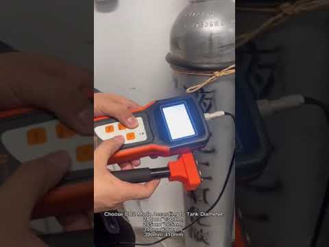
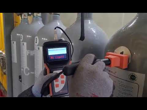
What Is the Ultrasonic CO2 Level Indicator? CO2 Bottle Level Measuring Device

What Is the Ultrasonic CO2 Level Indicator?

Ultrasonic CO2 Level Indicator is the best CO2 Bottle Level Measuring Device. Our product Portable Ultrasonic Liquid Level Indicator can effectively detect the storage capacity of the fire extinguishing agent storage container in the gas fire extinguishing system (such as: Proto-Indo-European, halo-alkane, CO2, etc.).
Our Portable Ultrasonic Liquid Level Indicator uses non-contact detection technology and is ideal for detecting hazardous toxic or corrosive liquids. It can be used to measure whether there is liquid at a certain height in a container or pipeline.

Portable Ultrasonic Level Indicator

Our Portable Ultrasonic Liquid Level Indicator for tank is designed to determine the presence or absence of the liquid at a certain height in a container or in pipeline. The liquid containers to be measured can be made of various kinds of materials such as metal, glass or un-foamed plastics.

Under ordinary conditions, the maximum wall thickness of measured containers is 30mm. The indicator can be used to detect various types of liquids (without crystallization or other particulate matter). Because of the innovative non-contact detection methods, this liquid level indicator is an ideal choice for the detecting dangerous toxic or corrosive liquids.

Features

  • No physical contact with medium
  • Suitable for toxic, corrosive, or invasive media
  • No need for drilling or welding on tank wall
  • Simple and convenient to operate and maintain
  • Ultrasonic adaptive detection algorithm.
  • High-contrast OLED color display, suitable for outdoor use under strong light
  • Intuitive user interface design
  • Comprehensive software displays measurements simply and clearly

Applicable CO2 Tanks/Cylinders/Bottles

CO2 Tank with any of the following diameter ranges:

210mm-230mm, 265mm-285mm, 340mm-360mm, 390mm-410mm

Common Tank: 

All tanks outside the above tank diameter ranges can be considered as common type.
vertical tank / horizontal tank / spherical tank(diameter <3M)
The indicator has no requirement towards medium, height and pressure.

Parameters

Measurement accuracy< 5mm
Measurable range of wall thickness3~30 mm
Measurable tank materialSteel, stainless steel, glass, unformed plastics
Measurable mediumPure liquid, milky liquid, suspension liquid
Ambient temperature-20℃〜60℃ (-4℉〜+140℉)
Ambient humidity15% ~ 85% RH
Power supplyTwo lithium batteries (supplied by customers)
Current100 mAh (on average)

Ultrasonic CO2 Level Indicator CO2 Tank Measurement

CO2 cylinder specifications (external diameter division):

The CO2 cylinders measured by this meter are divided into the following 4 specifications:

215mm-225mm diameter cylinders,
270mm-280mm diameter cylinders,
345mm-355mm diameter cylinders,
395mm-405mm diameter cylinders.

There are no excessive requirements for the height of the medium and the tank.

CO2 cylinder measurement operation:

  • Select “co2 cylinder”-“Choose a suitable cylinder diameter” through the menu and enter the measurement interface.
  • Hold the probe vertically and tightly on the tank, and press the button to measure.
  • Measurement results are based on measurement parameters and level indicator lights (red is “no liquid”, green is “with liquid”)
  • Generally, the measurement is started from the bottom of the storage tank (measurement with liquid position). If the measurement parameter is> = 2, the current level is considered to be a liquid-free position, and <2 is considered to be a liquid level; if it is floatingaround 2, It is considered that the liquid level of the horizontal plane is approaching the liquid surface (usually about 5 cm).
  • Take multiple points on the same horizontal plane for measurement, and take the result with the highest probability as the final result (avoid the interference of welds and unknown factors).
  • Find the liquid level position step by step through theapproximation measurement.

CO2 cylinder measurement Note:
Due to the irregular air outlet and a large number of welding kits at the top of the co2 cylinder, the measurement results at the bottom and top are invalid. (The top is generally empty in the case of a full tank).

Please refer to the video below to understand the operation tutorial and case of Ultrasonic CO2 Level Indicator.

In addition to Ultrasonic CO2 Level Indicator, we have more applications of ultrasonic technology.

More Ultrasonic Prodcuts

Our Sino-inst Ultrasonic CO2 Level Indicator stands as a symbol of safety, precision, and efficiency in industrial applications. This superior device excels in assessing fire extinguishing systems, accurately measuring storage capacity with its non-contact det ection technology. It is versatile, handling various agents like Proto-Indo-European, halo-alkane, and CO2.

The safety advantages of this tool are unmatched, as it ensures no direct contact with toxic or corrosive liquids. Industries that prioritize safety, accuracy, and reliability find enormous value in our Ultrasonic CO2 Level Indicator. Whether for regular monitoring or spot checks, it provides dependable data, ensuring operations run smoothly and safely. Trust the Ultrasonic CO2 Level Indicator – it’s your partner in precision.

Our Ultrasonic CO2 Level Indicator is widely sold to various countries in the world. As an excellent and portable CO2 Bottle Level Measuring Device, it provides convenience for various industries such as fire protection. If you need, please feel free to contact Sino-Inst!

Request a Quote

Please enable JavaScript in your browser to submit the form

Dew Point Monitor for the Fruit and Vegetable Industry

Dew point monitors play a pivotal role in the thriving world of the fruit and vegetable industry. It can make the difference between a fresh, quality harvest and a subpar one. The dew point, a measure of atmospheric humidity, impacts everything from farming and storage to transport and retail.

Accurate monitoring of the dew point helps manage moisture levels, ensuring optimal growing conditions and preserving freshness during storage and transport. More importantly, it safeguards the quality that consumers demand and expect.

What is Dew Point ?

Dew point is a term that might seem a bit scientific, but it’s quite simple once you break it down. Essentially, it’s the temperature at which the air becomes saturated with water vapor. When this happens, the vapor condenses into tiny drops of dew. You’ve probably noticed this phenomenon on cool mornings when you see droplets forming on the grass or on your car windows.

Why does the dew point matter, especially in the fruit and vegetable industry? Simply put, it’s all about controlling moisture. Just like us humans, fruits and vegetables are mostly water. So, they’re sensitive to the moisture in the air around them. If the air is too dry, they can shrivel and lose their freshness. But if it’s too humid, they can become overly moist and prone to rotting.

Advanced dew point monitors, like the ones our company provides, measure the air’s moisture content and temperature. They then use this information to calculate the dew point. With this data at your fingertips, you can ensure the best conditions for growing, storing, and transporting your fruits and vegetables.

Why Dew Point Monitoring is Essential for the Fruit and Vegetable Industry

Dew point monitoring holds a crucial role in the fruit and vegetable industry. It’s all about preserving that garden-fresh quality, from the field to the consumer’s table.

The dew point affects the quality of fruits and vegetables in several ways.

When the dew point is high, indicating a lot of moisture in the air, fruits and vegetables can absorb excess water. This might lead to faster spoilage and loss of firmness.

On the flip side, when the dew point is too low, the air is dry, which can cause fresh produce to lose moisture, shrivel up, and lose its appealing, fresh-picked look.

When it comes to storage and preservation, controlling the dew point is key. By monitoring the dew point, storage facilities can adjust humidity levels to prevent dehydration or over-saturation. This extends shelf life and maintains the appearance and nutritional value of the produce.

A prime example of dew point’s importance can be seen in apple storage. Apples are stored at low temperatures to extend their freshness. However, if the dew point isn’t carefully controlled, the cold environment could lead to condensation, a perfect breeding ground for molds and bacteria. By using dew point monitors, storage facilities can balance humidity, temperature, and dew point to prevent such issues and keep apples crisp and fresh for longer.

Through our dew point monitors, the fruit and vegetable industry can maintain this delicate balance and ensure the delivery of high-quality produce all year round.

Applications of Dew Point Monitors in the Fruit and Vegetable Industry:

Farming: Monitors provide real-time dew point data to help farmers optimize their irrigation schedules, preventing overwatering and under watering.

Transport: In climate-controlled vehicles, dew point monitors maintain optimal humidity levels, preventing produce from drying out or absorbing excess moisture during transport.

Storage: Monitors enable precise control of storage conditions, extending the freshness of produce, avoiding condensation, and preventing rot.

Benefits of Accurate Dew Point Monitoring:

Quality Assurance: Regular monitoring ensures the quality and longevity of produce from farm to table.

Efficiency: Minimizing spoilage and waste helps businesses run more efficiently.

Competitiveness: By delivering high-quality produce, businesses can gain a competitive edge in the market.

Sustainability: Efficient use of resources contributes to a more sustainable food system.

More Gas Detection Sloutions

Top 1 Guide to Dew Point Measurement

Dew point measurement, a simple concept that carries immense weight. Dew point, in layman’s terms, is the temperature at which the air can no longer hold all its water vapor and starts condensing – forming dew. Sounds simple, right? Yet, … Continue reading

What Is Zirconia Oxygen Sensor?

Welcome to the world of Zirconia Oxygen Sensors, a cornerstone of precision in process control and industrial efficiency. Oxygen plays a pivotal role in numerous industrial processes, making its precise monitoring critical. That’s where our focus, the zirconia oxygen sensor, … Continue reading

In conclusion, dew point monitoring is essential for the fruit and vegetable industry. It’s a vital tool at every stage, from farming and transport to storage. By maintaining optimal moisture levels, dew point monitors help ensure the freshness, quality, and longevity of produce.

Our dew point sensors at Sino-Inst bring this crucial monitoring to your fingertips. They offer precision, user-friendly interfaces, and seamless integration into your existing systems. But what sets us apart is our rich experience as a manufacturer and supplier, our dedication to quality, and our commitment to our customers.
Reach out to us at Sino-Inst, and let our team guide you to the right dew point monitoring solution for your needs.

Request a Quote

Please enable JavaScript in your browser to submit the form

Radar Level Gauge – Everything You Should Know and Selection List

Radar level gauges are an essential part of many industrial operations, serving as the invisible sentinels that accurately measure the levels of various substances. These sophisticated devices use cutting-edge radar technology to make precise, non-contact measurements. Capable of working seamlessly under a variety of challenging conditions, radar level gauges offer undeniable benefits in accuracy, reliability, and versatility.

Featured Radar Level Gauge Selection

Radar Level Gauge 11S
  • Measuring medium: Liquid
  • Measuring range: 0.1m~10m
  • Process connection: Thread G¾”A / ¾”NPT;Flange ≥DN25
  • Process temperature: -40~100℃
  • Process pressure: -0.1~1.6 MPa
  • Antenna size: 21mm lens antenna
  • Antenna material: PTFE
  • Accuracy: ±5mm
  • Protection level: IP67
  • Center frequency: 80GHz
  • Launch angle:14°
  • Power source:
    • Two-wire system/DC24V
    • Four-wire system/AC220V
    • Six-wire system/DC12-24V
  • Shell: Aluminum/Plastic/Stainless steel
  • Signal output:
    • Two-wire system/4…20mA/HART protocol
    • Four-wire system/4…20mA/HART protocol
    • Six-wire system/4…20mA/HART Protocol
Radar Level Gauge 11
  • Measuring medium: Liquid
  • Measuring range: 0.1m~30m
  • Process connection: Thread G½”A /1 ½”NPT; Flange ≥DN40
  • Process temperature: -40~80℃/ -40~100℃
  • Process pressure: -0.1~0.3 MPa
  • Antenna size:32mm lens antenna
  • Antenna material: PTFE
  • Accuracy: ±2mm
  • Protection level: IP67
  • Center frequency: 80GHz
  • Launch angle: 8°
  • Power source:
    • Two-wire system/DC24V
    • Four-wire system/AC220V
    • Six-wire system/DC12-24V
  • Shell: Aluminum/Plastic/Stainless steel
  • Signal output:
    • Two-wire system/4…20mA/HART protocol
    • Four-wire system/4…20mA/HART protocol
    • Six-wire system/4…20mA/HART protocol
Radar Level Gauge 12
  • Measuring medium: Liquid
  • Measuring range: 0.1m~30m
  • Process connection:Flange ≥DN40
  • Process temperature: -40~120℃
  • Process pressure: -0.1~1.6 MPa
  • Antenna size:32mm lens antenna
  • Antenna material: PTFE
  • Accuracy: ±2mm
  • Protection level: IP67
  • Center frequency: 80GHz
  • Launch angle: 8°
  • Power source:
    • Two-wire system/DC24V
    • Four-wire system/AC220V
    • Six-wire system/DC12-24V
  • Shell: Aluminum/Plastic/Stainless steel
  • Signal output:
    • Two-wire system/4…20mA/HART protocol
    • Four-wire system/4…20mA/HART protocol
    • Six-wire system/4…20mA/HART protocol
Radar Level Gauge 13
  • Measuring medium: Liquid
  • Measuring range: 0.2m~30m/0.3~150m
  • Process connection:Flange ≥DN80 /Thread G3 A
  • Process temperature:
    • -40~150℃
    • -40-130℃( Athread)
  • Process pressure: -0.1~1.0 MPa
  • Antenna size:76mm lens antenna
  • Antenna material: PTFE
  • Accuracy: ±2mm
  • Protection level: IP67
  • Center frequency: 80GHz
  • Launch angle: 3°
  • Power source:
    • Two-wire system/DC24V
    • Four-wire system/AC220V
    • Six-wire system/DC12-24V
  • Shell: Aluminum/Plastic/Stainless steel
  • Signal output:
    • Two-wire system/4…20mA/HART protocol
    • Four-wire system/4…20mA/HART protocol
    • Six-wire system/4…20mA/HART Protocol
Radar Level Gauge 13S
  • Measuring medium: Liquid
  • Measuring range: 0.2m~30m/0.3~150m
  • Process connection:Flange ≥DN80 /gantry frame
  • Process temperature: -40~80℃
  • Process pressure: -0.1~0.3 MPa
  • Antenna size:76mm lens antenna
  • Antenna material: PTFE
  • Accuracy: ±2mm
  • Protection level: IP67
  • Center frequency: 80GHz
  • Launch angle: 3°
  • Power source:
    • Two-wire system/DC24V
    • Four-wire system/AC220V
    • Six-wire system/DC12-24V
  • Shell: Aluminum/Plastic/Stainless steel
  • Signal output:
    • Two-wire system/4…20mA/HART protocol
    • Four-wire system/4…20mA/HART protocol
    • Six-wire system/4…20mA/HART Protocol
Radar Level Gauge 13G
  • Measuring medium: Liquid
  • Measuring range: 0.1m~30m/0.3m~150m
  • Process connection:Flange ≥DN80
  • Process temperature: -40~280℃
  • Process pressure: -0.1~2.5 MPa
  • Antenna size:76mm lens antenna
  • Antenna material: PEEK
  • Accuracy: ±2mm
  • Protection level: IP67
  • Center frequency: 80GHz
  • Launch angle:  6°
  • Power source:
    • Two-wire system/DC24V
    • Four-wire system/AC220V
    • Six-wire system/DC12-24V
  • Shell: Aluminum/Plastic/Stainless steel
  • Signal output:
    • Two-wire system/4…20mA/HART protocol
    • Four-wire system/4…20mA/HART protocol
    • Six-wire system/4…20mA/HART Protocol
Radar Level Gauge 14
  • Measuring medium: Liquid
  • Measuring range: 0.1m~30m
  • Process connection:Flange ≥DN50
  • Process temperature: -40~200℃
  • Process pressure: -0.1~2.5 MPa
  • Antenna size:44mm lens antenna
  • Antenna material: PTFE
  • Accuracy: ±2mm
  • Protection level: IP67
  • Center frequency: 80GHz
  • Launch angle:  6°
  • Power source:
    • Two-wire system/DC24V
    • Four-wire system/AC220V
    • Six-wire system/DC12-24V
  • Shell: Aluminum/Plastic/Stainless steel
  • Signal output:
    • Two-wire system/4…20mA/HART protocol
    • Four-wire system/4…20mA/HART protocol
    • Six-wire system/4…20mA/HART Protocol
Radar Level Gauge 15
  • Measuring medium: Liquid
  • Measuring range: 0.3m~30m
  • Process connection:Flange ≥DN80
  • Process temperature: -40~200℃
  • Process pressure: -0.1~2.5 MPa
  • Antenna size:76mm lens antenna
  • Antenna material: PTFE
  • Accuracy: ±2mm
  • Protection level: IP67
  • Center frequency: 80GHz
  • Launch angle:  3°
  • Power source:
    • Two-wire system/DC24V
    • Four-wire system/AC220V
    • Six-wire system/DC12-24V
  • Shell: Aluminum/Plastic/Stainless steel
  • Signal output:
    • Two-wire system/4…20mA/HART protocol
    • Four-wire system/4…20mA/HART protocol
    • Six-wire system/4…20mA/HART Protocol
Radar Level Gauge 21
  • Measuring medium: Solid
  • Measuring range: 0.1m~30m/0.3~150m
  • Process connection:Flange ≥DN80
  • Process temperature: -40~150℃/-40~200℃
  • Process pressure: -0.1~0.3 MPa
  • Antenna size:76mm lens antenna
  • Antenna material: PTFE
  • Accuracy: ±5mm
  • Protection level: IP67
  • Center frequency: 80GHz
  • Launch angle:  3°
  • Power source:
    • Two-wire system/DC24V
    • Four-wire system/AC220V
    • Six-wire system/DC12-24V
  • Shell: Aluminum/Plastic/Stainless steel
  • Signal output:
    • Two-wire system/4…20mA/HART protocol
    • Four-wire system/4…20mA/HART protocol
    • Six-wire system/4…20mA/HART Protocol
Radar Level Gauge 21S
  • Measuring medium: Solid
  • Measuring range: 0.1m~30m/ 0.3m~150m
  • Process connection:Flange ≥DN80
  • Process temperature: -40~80℃
  • Process pressure: -0.1~0.3 MPa
  • Antenna size:76mm lens antenna
  • Antenna material: PE
  • Accuracy: ±5mm
  • Protection level: IP67
  • Center frequency: 80GHz
  • Launch angle:  3°
  • Power source:
    • Two-wire system/DC24V
    • Four-wire system/AC220V
    • Six-wire system/DC12-24V
  • Shell: Aluminum/Plastic/Stainless steel
  • Signal output:
    • Two-wire system/4…20mA/HART protocol
    • Four-wire system/4…20mA/HART protocol
    • Six-wire system/4…20mA/HART Protocol

Radar Level Gauges Measurement Technology

The general principle of the FM continuous wave radar level gauge is that the radar emits electromagnetic waves on the top of the tank, and the electromagnetic waves are received by the radar after being reflected by the medium.

The frequency difference δf between the received signal and the transmitted signal is proportional to the distance R from the surface of the medium: R=C (speed)*δf (frequency difference)/2/K (frequency modulation slope).

Because the speed of light C and the frequency modulation slope K are known, the frequency difference δf can be estimated to obtain the distance R from the radar installation position to the material surface. And then through the known total height of the tank, subtract the spatial distance from the radar to the material surface (referred to as Empty height) to get the height of the material level.

Advantages of Using Radar Level Gauges

  1. Millimeter-wave radar, with a measurement accuracy of up to ±1mm, and a minimum blind area of 0.1m.
  2. The smaller antenna size satisfies the measurement of more working conditions.
  3. A variety of lens antennas, smaller launch angle, more concentrated energy, stronger echo signal, under the same industrial and mining conditions, compared to
    Other radar products have higher reliability.
  4. With stronger penetrability, it can be used normally even if there is adhesion and condensation.
  5. The dynamic signal range is larger, and the measurement of low dielectric constant medium is more stable.
  6. 6. A variety of measurement modes, the radar reaction time in the fast measurement mode is less than 1S.

Applications of Radar Level Gauges Across Industries

Radar Liquid Level Sensors

Radar liquid level sensors are special tools that use radio waves to measure how much liquid is in a tank…

Selection List

When choosing a radar level gauge, several factors need careful consideration to ensure that the gauge suits your specific requirements. Here’s a list to guide your selection process:

  • Nature of the Substance: The physical characteristics of the substance to be measured play a crucial role. Consider whether the substance is liquid or solid, its reflective properties, its density, and whether it is corrosive or otherwise hazardous.
  • Environmental Conditions: The conditions in which the gauge will operate can significantly affect its performance. Important conditions to consider include temperature, pressure, humidity, and the presence of dust or other particulates.
  • Installation Requirements: Gauge installation requirements, such as the size and shape of the tank or container, the presence of obstructions, and the available mounting options, can influence the choice of radar level gauge.
  • Range and Accuracy: Ensure the gauge has a measurement range that suits your needs. Also, consider the level of accuracy required for your operation.
  • Maintenance and Durability: Ideally, the gauge should require minimal maintenance and be durable enough to withstand your operating conditions for a reasonable period.
  • Cost: Finally, consider your budget. While higher-end models may offer advanced features and better performance, there might be cost-effective options that meet your requirements adequately.

Selecting the right radar sensor requires careful evaluation of your specific needs based on the sensor’s capabilities. Here we take the selection data of one of the radar level gauges FMW21/21s as an example.

 21/21s
ID:
License
P    Standard  (Non-explosion-proof)
I     Intrinsically safe(Exia IIC T6 Ga)
D    Flameproof(Ex db IIC T6 Gb)                                                                 
Process Connection / Material
1     Flange≥DN80              
X     Special customization
Antenna Type / Material
A  76mm Lens antenna / With purge port / PE
B  76mm Lens antenna / With purge port / PTFE
Sealing / process temperature
A    FKM/(-40-80℃)
B    FKM/(-40-150℃)
C    FKM/(-40-200℃)                              
Y     Special customization
he  Electronic Unit
1  (4~20)mA/HART protocol 24VDC   2-wire 
2  (4~20)mA/HART protocol 220VAC   4-wire   
3  (4~20)mA+RS485/Modbus protocol 12- 24VDC   6-wire                             
Shell material/protection grade
A   Cast aluminum / Single chamber / IP67
B   Cast aluminum / Double chamber / IP67
C   Cast aluminum / Double cavity side view / IP67
D   Plastic ABS / Single chamber / IP65
E   Stainless steel 304 / Single chamber / IP67
F    Stainless steel 304 / Double chamber / IP67
Cable Line
M   M20×l. 5
N    ½″ NPTX     Special customization  
Display programming
A    Programming with display
B    With display programming/ Bluetooth communication
C    Without          

Flange option / material

Specification / Code / MaterialPP UniversalPTFE UniversalStainless steel304 UniversalStainless steel316L Universal
DN80P4F4G4S4
DN100P5F5G5S5
DN125P6F6G6S6
DN150P7F7G7S7
DN200P8F8G8S8

More Featured Radar Level Meters

FAQ

A radar level gauge is an instrument used in various industries to measure the level of materials without making physical contact. It utilizes radar wave technology, emitting waves that bounce off the material surface and return to the gauge, enabling it to calculate the material’s level accurately.

Radar level measurement is known for its exceptional accuracy. While the exact degree of accuracy can vary depending on the specific model and operating conditions, most radar level gauges can achieve accuracy within a few millimeters.

There are mainly two types of radar level gauges: guided wave radar (GWR) and non-contact (or free-space) radar. GWR uses a probe to guide the radar waves to the material surface, while non-contact radar emits waves freely towards the material. Each type has its unique advantages and is suitable for different applications.

A radar level meter works by emitting radar waves towards the surface of the material being measured. These waves bounce back off the surface and are captured by the meter. By calculating the time it takes for the waves to travel to the surface and back, the meter can determine the level of the material accurately.

In conclusion, radar level gauges are a sophisticated and highly reliable tool for non-contact level measurement across diverse industries.

At Sino-Inst, we understand the vital role that accurate level measurement plays in your operations. We’re an experienced manufacturer and supplier of radar level gauges.

Whether you’re looking for standard options or require customized solutions to meet unique requirements, our team is ready to assist. We’re committed to delivering high-quality products that contribute to the efficiency and success of your business.

Request a Quote

Please enable JavaScript in your browser to submit the form

What Is a Dew Point Monitor and How to Choose One?

Dew point monitors are critical equipment in many industries. The dew point is the temperature at which the air humidity reaches saturation. A dew point monitor is the instrument that detects this temperature. Although dew point measurement is most often cited in weather forecasting, it is also an important factor in many industrial processes. Excessive moisture may impair product quality and performance as well as materials.

What is a Dew Point Monitor?

Dew point monitors are vital pieces of equipment used to measure the temperature at which the air becomes saturated, causing water vapor to condense into liquid. This temperature is known as the dew point. By monitoring this, we gain essential information about the humidity in a certain environment.

Why is this important? In many industries, excess moisture can pose significant problems. For example, in compressed air systems, high humidity can lead to corrosion in the pipelines. In the electronics industry, too much moisture can damage sensitive components. Similarly, in climate-controlled environments like laboratories, an accurate reading of the dew point is crucial for maintaining ideal conditions.

In essence, a dew point monitor gives us a precise, reliable way to keep track of humidity levels. By doing so, it helps prevent potential issues caused by moisture, ensuring everything runs smoothly in various environments where humidity control is critical.

how a dew point monitor works?

A dew point monitor works by examining the air or gas in an environment to determine the temperature at which it would be fully saturated, or, in other words, the temperature at which dew would form. This process might sound complex, but let’s simplify it a bit.

Picture a cool glass on a hot day. After a while, you’ll see droplets form on the outside of the glass. That’s condensation, which happens when the air around the cold glass cools down to a point where it can’t hold all its moisture. That exact temperature is the dew point.

Dew point monitors utilize advanced sensors to mimic this process. They chill a surface within the device and measure the temperature at which condensation begins to form on that surface. This temperature is reported as the dew point.

These devices work by cooling a mirror within the unit until condensation forms on its surface. The temperature at which this occurs is accurately measured and reported as the dew point. Chilled mirror dew point monitors are known for their high precision and reliability, making them ideal for laboratories and other settings where precise measurements are crucial.

These monitors measure the dew point by observing changes in electrical capacitance caused by variations in moisture content. They offer a good balance of accuracy and cost-effectiveness, suitable for many industrial applications.

These monitors work by measuring the changes in electrical resistance caused by humidity changes. They are generally cost-effective and provide reasonably accurate readings, making them popular in a variety of applications.

In short, dew point monitors give us an accurate way to measure the moisture content in the air, helping various industries prevent potential issues and maintain optimal conditions.

Technical Benefits of Dew Point Monitors

  • Precision: Dew point monitors offer highly accurate measurements of humidity levels, which is critical for many industrial and commercial operations.
  • Reliability: These devices provide reliable, consistent readings over time, supporting effective long-term humidity management.
  • Versatility: With the ability to operate across a wide range of temperatures and humidity levels, dew point monitors are useful in numerous industries and settings.
  • Preventive Maintenance: Dew point monitors facilitate timely interventions to avoid issues caused by excessive humidity, such as corrosion or equipment damage, leading to reduced maintenance costs and prolonged equipment lifespan.
  • Product Quality Enhancement: By controlling dew point, these monitors can directly improve the quality of products in various manufacturing settings, from food packaging to electronics storage.
  • Energy Efficiency: Especially in systems like compressed air dryers, dew point monitors help to regulate energy usage, thereby enhancing efficiency and reducing operational costs.

So, when we consider these substantial technical benefits, it becomes clear that dew point monitors play a vital role in managing optimal environmental conditions across a range of applications.

different industrial applications

Monitoring dew point is crucial across a variety of industries due to its impact on processes, product quality, and energy efficiency. Dew point monitors play a central role in this endeavor. Let’s delve into a few specific industries and applications:

HVAC and Building Management: In this field, dew point monitoring helps maintain comfortable and healthy indoor air quality. It also prevents condensation on surfaces, which can lead to mold growth and structural damage.

Pharmaceuticals and Healthcare: In pharmaceutical manufacturing and storage, maintaining a precise humidity level is critical to product quality and safety. Dew point monitors aid in ensuring these stringent conditions are met consistently.

Food and Beverage Industry: Here, dew point monitoring helps prevent condensation on machinery and packaging. This reduces the risk of microbial growth, ensuring the hygienic handling and quality of food products.

Electronics Manufacturing: In the production and storage of electronic components, maintaining a low dew point prevents moisture-related damage and improves product lifespan and reliability.

Compressed Air Systems: Dew point monitors ensure that the air used in these systems is dry enough to prevent pipeline corrosion and blockages from ice or condensed water.

Petrochemicals and Natural Gas: For these industries, dew point monitoring is critical for process control and safety, as excess moisture can lead to pipeline corrosion and efficiency loss.

In conclusion, the role of dew point monitors extends far beyond simple humidity measurement. They provide an essential service to a variety of industries, ensuring product quality, process efficiency, and operational safety. The right dew point monitoring can indeed make a significant difference in your industry or application.

How to Choose a Dew Point Monitor

Choosing a dew point monitor can feel like a daunting task, but with the right approach, it can be made simpler. Here’s a step-by-step guide to help you make the right decision:

  1. Understand Your Needs: The first step is understanding your specific requirements. What range of temperatures and humidity levels do you need to monitor? What accuracy level is required? The answers to these questions will help you narrow down your options.
  2. Consider Your Industry Requirements: Different industries have different standards and requirements when it comes to dew point monitoring. Ensure that the monitor you choose meets or exceeds these industry-specific standards.
  3. Budget Constraints: Dew point monitors come at varying price points, depending on their features and technology. It’s essential to balance the need for quality and accuracy with your available budget.
  4. Evaluate Features: Look for features that make the monitor easier to use and more efficient. This could include easy-to-read displays, connectivity options for remote monitoring, self-calibration features, and more.
  5. Research Brands and Models: There are many dew point monitor brands and models on the market. Spend some time researching and comparing them. Look at customer reviews and ratings to get a sense of their reliability and performance.
  6. Consider After-sales Service and Support: Good after-sales service, including technical support and warranty, can be a lifesaver if you encounter issues with the monitor.

By following these steps, you can make an informed decision and choose a dew point monitor that meets your specific needs and industry requirements, while fitting within your budget. Remember, the right dew point monitor is not just a purchase – it’s an investment in quality control and efficient operations.

More Gas Detection Sloutions

What Is Zirconia Oxygen Sensor?

Welcome to the world of Zirconia Oxygen Sensors, a cornerstone of precision in process control and industrial efficiency. Oxygen plays…

In conclusion, dew point monitors are vital instruments in a variety of industries, from HVAC and building management to pharmaceuticals, food and beverage, and beyond.

Choosing the right dew point monitor is an investment that can yield significant returns in terms of improved process control, product quality, and operational efficiency.

Sino-Inst invite you to explore our range of dew point monitors. Each of our products has been carefully designed to provide accuracy, reliability, and ease of use in mind. If you have any questions or need more personalized advice, don’t hesitate to contact us. We’re here to help you make the right choice for your specific needs and requirements.

Request a Quote

Please enable JavaScript in your browser to submit the form

What Are Flow elements? Guide for Different Types of Flow Elements

What are flow elements? Simply put, a flow element is a device used to measure the rate at which a fluid (like water or gas) moves through a pipeline. Imagine a highway, and the flow element is the toll booth that monitors how many cars pass through. Only instead of cars, flow elements deal with the movement of fluid.

Types of Flow Elements

Understanding flow elements can feel like an adventure, with each type having its own unique characteristics and applications. Let’s delve into nine different types of flow elements, each offering unique advantages and suited to various applications.

Pitot Tube

The Pitot Tube, named after the French engineer Henri Pitot, measures the velocity of fluid flow by comparing the fluid’s static pressure to its dynamic pressure. These devices are simple, cost-effective, and ideal for applications where minimizing pressure loss is crucial.

Annubar Flow Element

Annubar Flow Elements, also known as averaging pitot tubes, have a distinct multiport design. They provide an averaged differential pressure output that allows for a more accurate measurement of flow rates, particularly in larger pipes and ducts.

Target Flow Sensor

Target Flow Sensors work a little differently. A ‘target’ (essentially a disc) is placed in the fluid flow, and as the fluid hits this target, it creates a force. By measuring this force, we can calculate the flow rate. These sensors are robust and can measure flow in both directions, making them versatile options.

Venturi Tube

Venturi Tubes are designed for accuracy. They feature a distinct tube that first narrows, then widens. The fluid accelerates in the narrow section and decelerates in the wider section. This change in speed alters the pressure, which is used to calculate flow rate. If precision is your top priority, Venturi Tubes are worth considering.

Flow Nozzle

Flow Nozzles are the resilient heroes of the flow element world. Their durable design can handle high-speed flows and harsh conditions, like high temperatures in steam flows. If toughness is paramount, Flow Nozzles step up to the plate.

V Cone Flow Sensor

V Cone Flow Sensors are innovative devices that contain a cone inside the tube. As the fluid flows around the cone, it creates a differential pressure, which can be measured to calculate the flow rate. These sensors are known for their accuracy and are especially useful in difficult conditions, such as low-reynolds-number flows.

Segmental Wedge Flow Element

Segmental Wedge Flow Elements have a distinct, wedge-shaped restriction that generates a differential pressure, measuring the flow rate. They’re particularly effective for sludges, slurries, and other flows with a high solids content, which can pose challenges for other flow elements.

Elbow Flow Element

Elbow Flow Elements take advantage of a simple fact: fluid turning a corner creates a pressure drop. By placing a sensor on the inside and outside of the elbow, we can measure this pressure drop and calculate the flow rate. These devices are useful when space is limited.

Orifice Plate Throttle

Orifice Plate Throttles are one of the simplest and most widely used flow elements. They involve a flat plate with a hole in the middle, placed within the pipe. The pressure change as fluid flows through this hole gives us the flow rate. Simple, reliable, and cost-effective, these devices are a go-to in many industries.

Remember, choosing the right flow element depends on your specific needs, conditions, and the nature of your fluid. By understanding these different types, you’re well-equipped to make an informed decision. So, let’s continue to dive deeper into the world of flow elements!

Understanding Flow Rates and Measurements

Flow rate is crucial in a multitude of industries, including manufacturing, oil production, and water treatment, to name just a few. But how do we measure it? That’s where flow elements and the concept of differential pressure come in.

Flow elements are devices that create a change, or a difference, in pressure as the fluid passes through them – hence the term ‘differential pressure.’ Think of sticking your hand out of the window of a moving car. When you hold your hand flat, parallel to the ground, you feel a certain amount of pressure from the wind. Now, tilt your hand – the pressure changes. Flow elements create and measure this change in pressure, and from it, they can calculate the flow rate.

This is the basic principle behind differential pressure flow meters. These devices consist of a flow element, which creates a pressure drop, and a transducer, which measures this drop. The greater the flow, the larger the pressure drop, and vice versa.

Top Flow Element Products

Applications of Flow Elements

Flow elements might be small, but they play a massive role in many industries worldwide. Let’s explore some of the applications where flow elements make a significant difference.

In the oil and gas industry, flow elements are vital. They help measure the flow rates of oil, natural gas, and other fluids in pipelines, helping companies monitor production, detect leaks, and ensure safe and efficient operations.

In wastewater treatment, flow elements measure the rate of flow of wastewater and other fluids, crucial for effective treatment and processing. They help control the treatment processes, ensuring that the right amount of water is treated and that the treatment chemicals are added in the correct quantities.

In HVAC systems, flow elements measure the flow rate of air and other gases. This data allows for the control and optimization of these systems, ensuring that buildings are kept at the right temperature and humidity levels.

The food and beverage industry also relies heavily on flow elements. They measure the flow rate of various liquids, from water used in cleaning processes to the liquids that make up our favorite drinks. These measurements ensure product quality and consistency, and help with portion control.

In the pharmaceutical industry, flow elements play a crucial role in ensuring that the right quantities of fluids are used in the production of medicines. This is crucial for product quality and safety, as well as for meeting strict industry regulations.

So, there you have it! From the oil in our cars to the air in our homes, the water in our cities to the drinks in our fridge, flow elements are hard at work. These small devices play a big role in making our world run smoothly.

FAQ

Flow elements are devices used to measure the rate at which a fluid, like a gas or a liquid, is flowing through a pipe or conduit. They create a change in pressure as the fluid flows through them. This pressure change, known as differential pressure, is then measured and used to calculate the flow rate.

The primary purpose of a flow element is to create a pressure difference, or differential pressure, within a fluid flow. By creating this pressure difference and measuring it, flow elements can calculate the rate at which the fluid is flowing. This is vital for controlling and optimizing many processes across various industries, such as manufacturing, oil and gas, water treatment, and more.

The working principle of a flow element involves creating and measuring a change in pressure. As a fluid flows through the flow element, it causes a pressure drop. This pressure drop is proportional to the square of the flow rate. By measuring this pressure drop, the flow element can calculate the rate of fluid flow.

A flow sensing element is another term for a flow element. It’s a part of a flow meter that creates a change in pressure, measures this pressure change, and uses the measurement to calculate the rate of fluid flow. This information is essential for a wide variety of applications, from managing water supplies to controlling industrial processes.

More Flow Measurement Solutions

What Is a Doppler Flow Meter?

Doppler Flow Meter is a new type of non-contact ultrasonic flow meter. Installs completely outside the pipe, eliminating the need…

Remember that not all flow elements are created equal. Choosing the right type for your specific needs and conditions is vital. Whether it’s an Orifice Plate, a Venturi Tube, a Pitot Tube, or any other type, each offers unique advantages and capabilities.

At Sino-Inst, we bring a wealth of experience as manufacturers and suppliers in this domain. We offer a wide range of flow elements, and we stand ready to customize solutions that meet your unique requirements. Our mission is to help you navigate the complexities of flow measurements with ease and confidence.

Request a Quote

Please enable JavaScript in your browser to submit the form

Innovative Methods for Fluid Level Measurement

Fluid level measurement is a crucial, yet often overlooked, process spanning various industries, from manufacturing to oil and gas. Methods for measuring fluid levels have come a long way, evolving from basic sight glass to advanced techniques like ultrasonic or radar measurement. Each method has its merits, and the choice often hinges on the specific scenario. Join us as we delve into these fascinating techniques, their advantages and shortcomings, in our comprehensive guide to fluid level measurement.

The Basics of Fluid Level Measurement

Let’s take a step back and delve into what fluid level measurement truly entails. The fluid can be anything – water in a reservoir, oil in a barrel, or a beverage in a production line. And the ‘tool’ we’re referring to? That’s the method of measurement.

Selecting the right method isn’t a random choice but requires careful consideration of both the fluid (target medium) and the container (vessel). Why? Because different fluids and containers can impact the measurement’s accuracy. Think about it this way – measuring the level of water in a glass is a much simpler task than assessing oil quantity in a massive industrial tank. The right method ensures the measurements are not only accurate but precise.

Now, let’s briefly introduce the main methods used for this purpose. There are six principal techniques, each boasting its unique strengths and limitations:

  • Continuous Float Level Transmitters: Utilizes a float that moves with the fluid level, providing continuous measurement.
  • Differential Pressure Transmitters: Measures the pressure difference at two points in the fluid, correlating it with the fluid level.
  • Load Cells: Uses force measurement to deduce the fluid level.
  • Radar Level Transmitters: Leverages radio wave technology to determine the fluid’s distance from the sensor, thus the fluid level.
  • Radio Frequency (RF) Capacitive Level Transmitters: Employs the change in capacitance caused by the change in fluid level to provide measurement.
  • Ultrasonic Level Transmitter: Sends ultrasonic pulses towards the fluid surface and calculates the fluid level based on the time it takes for the pulses to return.

With the basics covered, let’s delve deeper into these methods, their applications, and how to decide which one is the ‘perfect tool’ for your ‘task’. Stay tuned!

Traditional Methods of Fluid Level Measurement

Before we journey into the modern age of fluid level measurement, it’s worth taking a moment to appreciate the tried-and-true traditional methods that have served various industries for decades. Two of the most common methods include sight glass and hydrostatic pressure measurements.

Sight Glass Measurement

The sight glass method is a simple yet effective method for fluid level measurement. Picture a transparent tube attached to a tank, with the fluid level in the tube reflecting the fluid level in the tank. By observing the fluid in the sight glass, operators can visually estimate the fluid level in the tank.

The pros of this method are its simplicity and directness. There’s no need for complex calculations or advanced technology, making it both reliable and cost-effective. It’s especially useful for tanks containing multiple liquids of different densities, as the distinct separation layers can be easily seen.

However, the sight glass method also has its cons. Its simplicity can be a limitation in situations where precise measurement is necessary. Furthermore, it can be challenging to use in high-pressure tanks or with opaque or highly viscous fluids. Also, the physical wear and tear on the sight glass can lead to reading inaccuracies over time.

Hydrostatic Pressure Measurement

Hydrostatic pressure measurement operates on the principle that the pressure at any point in a fluid is directly proportional to its height. Thus, by measuring the pressure at the bottom of a tank, we can calculate the fluid’s height.

One of the key advantages of this method is its versatility. It can measure fluid levels in both open and closed tanks and handle various fluid types, from water to oil. Additionally, it offers consistent readings and can handle extreme temperatures and pressures.

Nevertheless, the hydrostatic method is not without its drawbacks. Changes in the fluid density can affect the accuracy of readings. Moreover, it requires regular maintenance and calibration to ensure accurate measurements, especially when dealing with corrosive or high-temperature fluids.

These traditional methods have laid a strong foundation for fluid level measurement. However, as with any technology, advancements were inevitable and necessary. Next, we’ll look at more sophisticated methods that leverage technological progress to improve accuracy and versatility in fluid level measurement. Stay with us!

Advanced Techniques in Fluid Level Measurement

Technological advancements have gifted the world of fluid level measurement with high-precision tools like ultrasonic sensors, radar measurement devices, and capacitive level transmitters. These tools elevate our ability to track fluid levels accurately and efficiently. Let’s learn more about them.

Ultrasonic Level Measurement

Ultrasonic level measurement capitalizes on sound wave technology. An ultrasonic sensor, located at the top of a tank, sends sound waves downward. When these waves hit the fluid surface, they bounce back to the sensor. The sensor then calculates the time taken for this round trip, which directly relates to the fluid level.

Pros: Ultrasonic sensors are non-contact devices, making them perfect for hazardous or corrosive fluids. These sensors are highly accurate and work well under various environmental conditions.

Cons: However, factors like a foamy fluid surface, intense turbulence, or heavy vapors can hamper the accuracy of ultrasonic measurements. Also, ultrasonic sensors are generally more expensive than traditional measurement methods.

Radar Level Measurement

Radar level measurement also uses the principle of echo, but instead of sound waves, it employs radio waves. These waves are released by a radar sensor, bounce off the fluid surface, and return to the sensor. The duration of this round trip helps calculate the fluid level.

Pros: Radar sensors are extremely accurate and can operate under a wide range of temperatures and pressures. They offer non-contact measurement, which is advantageous when dealing with dangerous or corrosive fluids.

Cons: While highly reliable, radar sensors are complex and more costly to install and maintain. They may also encounter difficulties in tanks with heavy internal structures due to signal interference.

Capacitive Level Measurement

Capacitive level measurement works by detecting changes in an electric field. A probe inserted into a tank forms one plate of a capacitor, with the tank wall (or a reference probe) serving as the other plate. As the fluid level changes, the dielectric constant changes, leading to a change in capacitance which can be measured and related to the fluid level.

Pros: Capacitive level transmitters are versatile, able to measure the levels of a wide range of fluids, including those that are corrosive, viscous, or have a low dielectric constant. They also function well in high-pressure or high-temperature environments.

Cons: However, they can be influenced by buildup on the probe or changes in the fluid’s dielectric constant. They also require regular calibration for maintaining their accuracy.

With these advanced techniques at our disposal, the landscape of fluid level measurement has broadened, offering more precision and flexibility than ever before. However, choosing the right method always depends on your specific requirements. In the following section, we’ll help guide you in making this choice. Stay tuned!

Choosing the Right Method for Fluid Level Measurement

In the world of fluid level measurement, some factors will influence the selection.

Type of Fluid: Different fluids have different properties that can affect the measurement accuracy. For instance, ultrasonic sensors may not be the best choice for highly viscous or foamy fluids due to signal dispersion. For such fluids, capacitive level transmitters might offer more reliable results.

Size of the Container: The size and shape of the container can also influence the choice of measurement method. For example, sight glass measurement might be perfect for small tanks, while radar or ultrasonic measurements could be better suited for large industrial tanks.

Environmental Conditions: The measurement method must also take into account environmental conditions. If the tank is in a high-temperature or high-pressure environment, robust methods like hydrostatic pressure or capacitive level measurement would be advantageous.

Industry Requirements: Lastly, industry-specific needs play a role. For instance, in the food and beverage industry, non-contact methods are often preferred to prevent contamination. While in the oil and gas industry, methods capable of withstanding corrosive materials are necessary.

More Level Measurement Solutions

Radar Liquid Level Sensors

Radar liquid level sensors are special tools that use radio waves to measure how much liquid is in a tank…

In conclusion, there’s no one-size-fits-all solution in fluid level measurement. It’s a careful selection process that requires a deep understanding of the application, environment, and industry needs. By considering these factors and weighing the pros and cons of each method, you can make an informed decision that ensures accurate, reliable, and efficient fluid level measurement.

The world of fluid level measurement is both vast and varied. From traditional methods like sight glass and hydrostatic pressure to modern techniques employing ultrasonic, radar, and capacitive technologies, the tools at our disposal are as diverse as they are dynamic.

With Sino-Inst by your side, you get more than just a product – you get a commitment to quality, a dedication to precision, and most importantly, a partner who understands and respects the importance of your work.

Ready to take the next step in your fluid level measurement journey? Get in touch with us today. Let’s explore the possibilities together and unlock the full potential of fluid level measurement for your operations.

Contact Sino-Inst: Your trusted partner in fluid level measurement.

Request a Quote

Please enable JavaScript in your browser to submit the form