Coriolis Mass Flowmeter is The Gold Standard in Modern Flow Measurement.
In today’s fast-paced industries, accurate flow measurement is pivotal. It’s the cornerstone for a myriad of vital tasks, from perfecting recipe formulations to ensuring transparent billing operations. The Coriolis Mass Flowmeter emerges as a leading solution amidst this backdrop, known for its impeccable reliability and precision. As industry demands grow, understanding the role and significance of this innovative tool becomes essential for anyone in the sector.
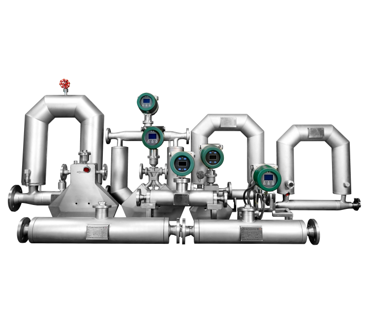
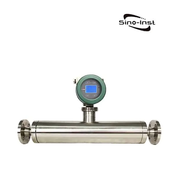
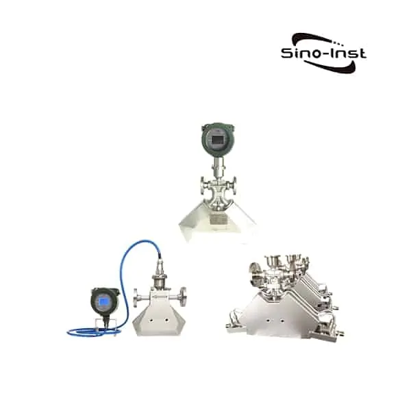
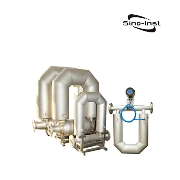
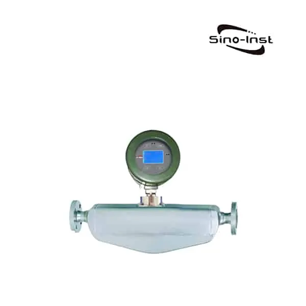
Featured Coriolis Mass Flowmeters
What is a Coriolis Mass Flowmeter?
The Coriolis mass flowmeter is an instrument that uses the principle of Coriolis force proportional to the mass flow generated by the fluid flowing in the vibrating tube to directly measure the mass flow.
There are two parallel flow tubes inside the sensor, with a driving coil in the middle and a detection coil at both ends. The detection coils installed at both ends of the vibrating tube will generate two sets of signals with different phases. The phase difference between the two signals is proportional to the mass flow rate of the fluid flowing through the sensor. The computer calculates the mass flow rate flowing through the vibrating tube.
When different media flow through the sensor, the main vibration frequency of the vibrating tube is different, and the density of the media is calculated accordingly. The platinum resistance installed on the vibration tube of the sensor can indirectly measure the temperature of the medium.
The Coriolis mass flowmeter has high measurement accuracy, and the measurement is not affected by the physical properties of the medium. There is no requirement for the length of the upstream and downstream straight pipe sections.
The Coriolis mass flowmeter can measure the density of the medium and indirectly measure the temperature of the medium.
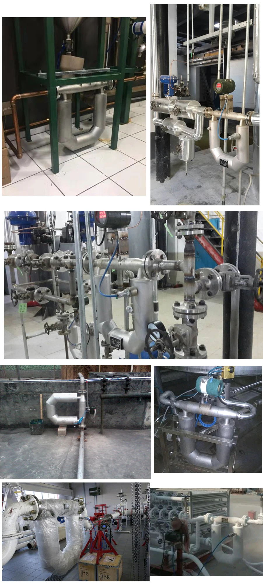
Coriolis mass flowmeters are widely used in chemical, pharmaceutical, energy, rubber, paper, food and other industrial sectors.
History of Mass Flow Measurement
Long before the rise of our modern industries, people recognized the need to measure the flow of liquids and gases. In ancient civilizations, farmers would gauge the flow of water into their fields using simple channels and markings. As time progressed, so did our methods.
By the Industrial Revolution, the need for precise flow measurement became critical. Factories required exact amounts of steam, water, and other fluids to power machinery and produce goods. This pushed inventors to create more advanced tools.
Enter the 20th century, and we witnessed a breakthrough: the Coriolis Mass Flowmeter. Using the Coriolis Effect, it offered an accuracy and versatility unmatched by older methods. Today, it stands as a testament to our journey from basic channels to sophisticated devices, ensuring industries everywhere run efficiently and effectively.
The Coriolis Principle
G.G. Coriolis, a French engineer, noticed that objects moving on Earth’s surface shift sideways. This happens because the planet rotates eastward. In the Northern Hemisphere, the deflection is to the right of the motion; in the Southern Hemisphere, the deflection is to the left. This drift plays a principal role in both the tidal activity of the oceans and the weather of the planet. A point on the equator traces a bigger circle each day than a point near the poles. When an object moves towards a pole, it turns eastward because it maintains its faster speed as it moves across the Earth’s surface. This drift is defined as the Coriolis force.
When a fluid is flowing in a pipe and it is subjected to Coriolis acceleration through the mechanical introduction of apparent rotation into the pipe, the amount of deflecting force generated by the Coriolis inertial effect will be a function of the mass flow rate of the fluid. If a pipe is rotated around a point while liquid is flowing through it (toward or away from the center of rotation), that fluid will generate an inertial force (acting on the pipe) that will be at right angles to the direction of the flow.
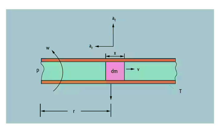
With reference to the picture above, a particle (dm) travels at a velocity (V) inside a tube (T). The tube is rotating about a fixed point (P), and the particle is at a distance of one radius (R) from the fixed point.
The particle moves with angular velocity (w) under two components of acceleration, a centripetal acceleration directed toward P and a Coriolis acceleration acting at right angle to ar:
ar (centripetal) = w2r
at (Coriolis) = 2wv
In order to impart the Coriolis acceleration (at) to the fluid particle, a force of at (dm) has to be generated by the tube.
The fluid particle reacts to this force with an equal and opposite Coriolis force:
Fc = at(dm) = 2wv(dm)
Then, if the process fluid has density (D) and is flowing at constant speed inside a rotating tube of cross-sectional area A, a segment of the tube of length X will experience a Coriolis force of magnitude:
Fc = 2wvDAx
Because the mass flowrate is dm = DvA, the Coriolis force Fc = 2w(dm)x and, finally:
Mass Flow = Fc / (2wx)
This is how measurement of the Coriolis force exerted by the flowing fluid on the rotating tube can provide an indication of mass flowrate.
While rotating a tube is not necessarily practical standard operating procedure when building a commercial flow meter, oscillating or vibrating the tube – which is practical – can achieve the same effect.
How Does a Coriolis Flow Meter Work?
When a particle located in a tube that rotates with P as a fixed point (rotation center) moves toward or away from the rotation center, an inertial force will be generated. The principle is shown in the figure:

In the figure, the particle with mass δm moves to the right in the pipe at a constant speed υ. The pipe rotates around a fixed point P at an angular velocity ω. At this point the particle will acquire two acceleration components:
- The normal acceleration αr (centripetal acceleration), its magnitude is equal to ω2r, and its direction is towards point P.
- Tangential acceleration αt (Coriolis acceleration), its magnitude is equal to 2ωυ, and its direction is perpendicular to αr.
The force generated by tangential acceleration is called Coriolis force, and its magnitude is equal to Fc=2ωυδm.
In the figure fluid δm=ρA×ΔX,
So the Coriolis force can be expressed as:
ΔFc=2ωυ×δm=2ω×υ×ρ×A×ΔX=2ω×δqm×ΔX
where A is the cross-sectional area of the pipe
δqm=δdm/dt=υρA
For a specific rotating pipe, its frequency characteristic is certain. ΔFc only depends on δqm.
Mass flow can therefore be measured directly or indirectly by measuring the Coriolis force.
The Coriolis principle mass flowmeter works according to the above principle.
The actual flow sensor does not achieve rotational motion, but pipe vibration instead.
Its principle diagram is shown in the figure below.
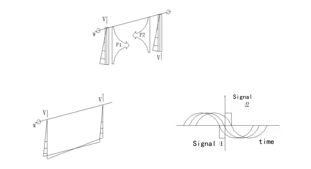
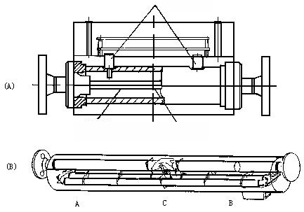
The two ends of a curved pipe are fixed, and a vibration force (according to the resonant frequency of the pipe) is applied to the pipe at the middle position of the two fixed points. Make it vibrate at its natural frequency ω about the fixed point as the axis.
When there is no fluid flow in the pipeline, the pipeline is only affected by the external vibration force. The two half-sections of the pipeline vibrate in the same direction and there is no phase difference.
When there is fluid flow, it is affected by the Coriolis force Fc of the medium particle flowing in the pipeline (the Coriolis forces F1 and F2 in the two half sections of the pipeline are equal in size and opposite in direction). The two halves of the pipe twist in opposite directions, creating a phase difference. This phase difference is proportional to the mass flow rate.
The design of the sensor is to convert the measurement of the Coriolis force into the measurement of the phase time difference on both sides of the vibrating tube, which is the working principle of the Coriolis mass flowmeter.
Coriolis Mass Flowmeter Tube Designs
Early designs of Coriolis mass flow meters were constructed to feed the flowing fluid through a pipe into a rotating system. The mass flow is measured by a torque sensor installed on the shaft. This flowmeter has only been trial-produced in the laboratory.
In a commercial product design, it is impractical to generate the Coriolis force through the rotation of the measurement system. Therefore, the method of vibrating the measuring tube is used instead of the rotary motion. In this way, the effect of the Coriolis force on the measuring tube is also realized, and the measuring tube is displaced under the action of the Coriolis force.
Since the two ends of the measuring tube are fixed, the force acting on each point on the measuring tube is different, and the resulting displacements are also different. An additional twist is thus formed on the measuring tube. By measuring the phase difference at different points in this twisting process, the mass flow rate of the fluid flowing through the measuring tube can be obtained.
Our common forms of measuring tubes are as follows:
- S-shaped measuring tube,
- U-shaped measuring tube,
- Double J-shaped measuring tube,
- B-shaped measuring tube,
- Single straight tube measuring tube,
- Double straight measuring tube,
- Ω-shaped measuring tube,
- Double ring measuring tube, etc.;
Below we give a brief introduction to their structures.
More Featured Flow Meters and Flow Measurement Solutions
What Are Flow elements? Guide for Different Types of Flow Elements
What Is a Doppler Flow Meter?
Top Liquid Flow Meters in Industry
Exploring the Different Types of 1 Inch Flow Meters
Flow Meter Selection Guide 101: Find the Perfect Fit for Your Application
Top Industrial Heating Oil Flow Meters
We, Sino-Inst, are the manufacturer of Coriolis Mass Flowmeters. Our Coriolis mass flow meter products directly and accurately measure the mass flow, density and temperature of fluids in closed pipes. The main types that are selling well are U series (U-shaped tube), T series (triangular shape), Z series (straight tube shape) and so on.
Universal measuring principle for liquids and gases
Multivariable measurement: Simultaneous measurement of mass flow, density, temperature and viscosity
High measurement accuracy: ±0.2% typ.; optional: ±0.1%
The measuring principle is completely independent of the physical properties of the fluid and the flow field
No front/rear straight pipe length requirements
Wide range of measurement range: 1:10,1:20
Our Coriolis Mass Flowmeter, from DN03~DN250. Widely exported and sold to various countries. If you need to measure mass flow, density, temperature and other parameters. Please feel free to contact our sales engineers!
Request a Quote

Wu Peng, born in 1980, is a highly respected and accomplished male engineer with extensive experience in the field of automation. With over 20 years of industry experience, Wu has made significant contributions to both academia and engineering projects.
Throughout his career, Wu Peng has participated in numerous national and international engineering projects. Some of his most notable projects include the development of an intelligent control system for oil refineries, the design of a cutting-edge distributed control system for petrochemical plants, and the optimization of control algorithms for natural gas pipelines.

