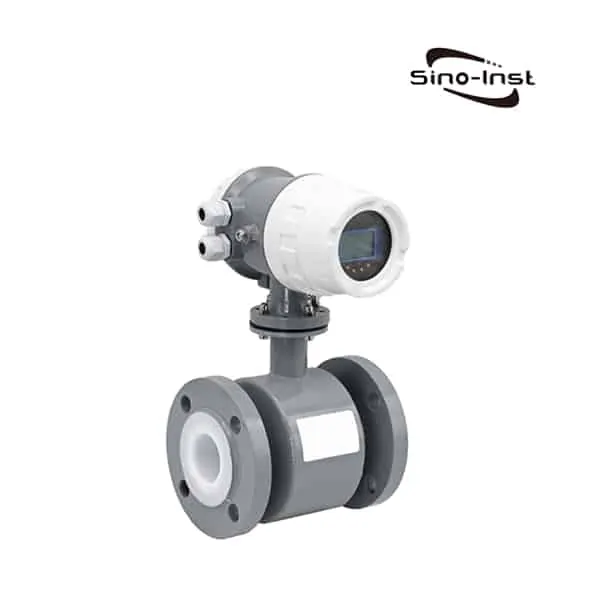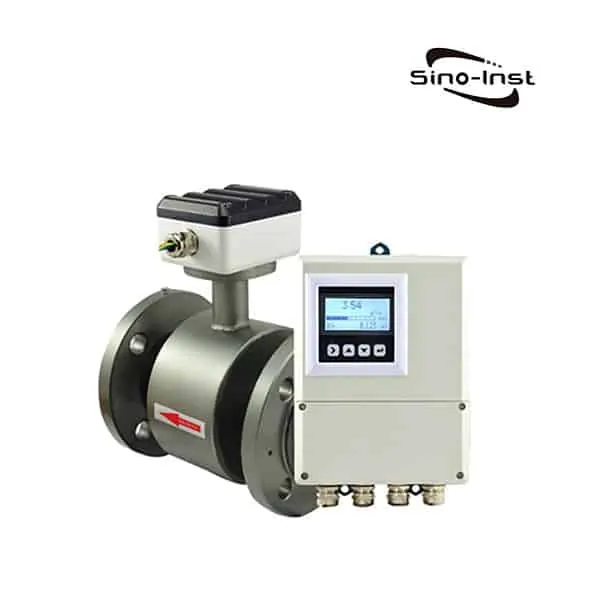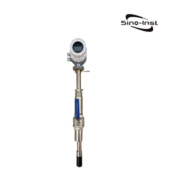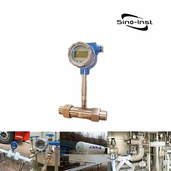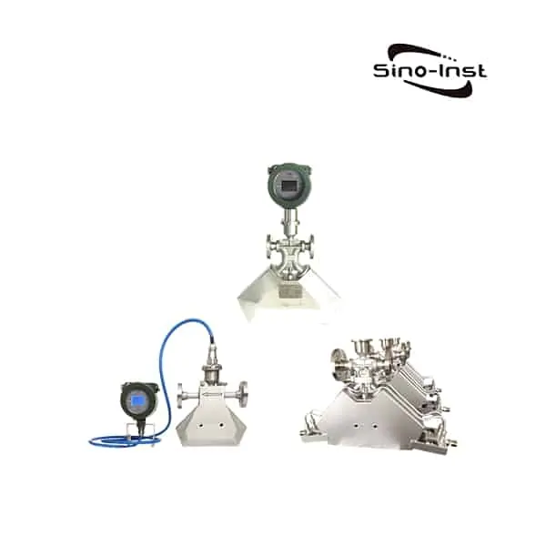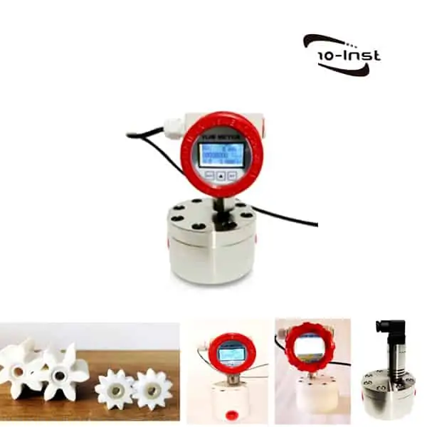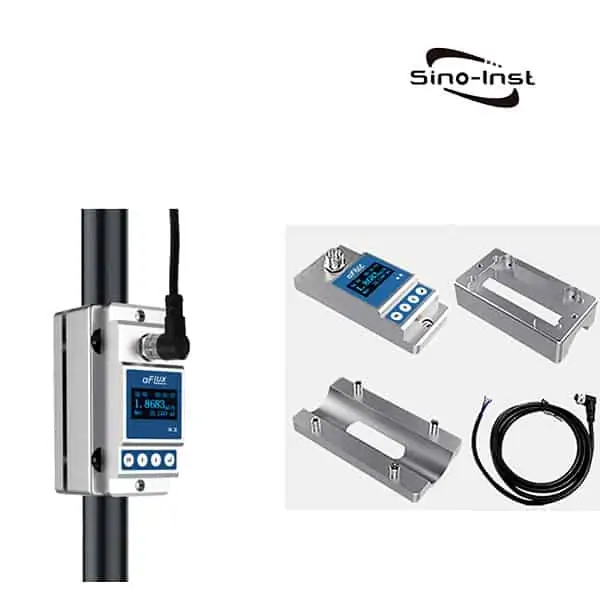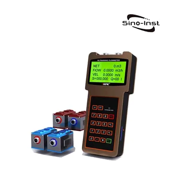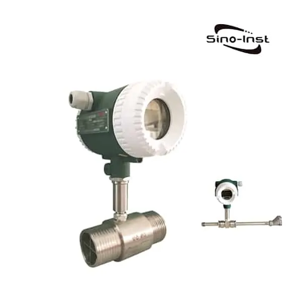
Turbine Pulse Flow Meter refers to a turbine flow meter that can be configured with pulse output. DN4~DN300, 304 stainlees steel, 316 stainlees steel, PE materials are available. It is widely used in measuring the flow of various liquids, including water, aqueous solution, hydraulic oil, etc.
The turbine flowmeter outputs pulse signal is used to detect the instantaneous flow rate and the total integrated flow rate. And is suitable for use with computer control systems such as secondary displays, PLCs, and DCS.
Turbine Pulse Flow Meter is a low-cost flow meter, reference price: USD 300-700/pc.
Sino-Inst offers a variety of Turbine flow meters for flow measurement. If you have any questions, please contact our sales engineers.
Features of Turbine Pulse Flow Meter
- High accuracy. Generally up to ±1%R, ±0.5%R;
- Good repeatability. Short-term repeatability can reach 0.05%~0.2%;
- Output pulse frequency signal. Suitable for total measurement and connection with computer. No zero drift, strong anti-interference ability;
- High frequency signals (3~4kHz) can be obtained, with strong signal resolution;
- Wide range. Medium and large diameters can reach 1:20. Small diameters are 1:10;
- Compact and lightweight structure. Easy installation and maintenance, large circulation capacity;
- Suitable for high-pressure measurement. No holes are required on the meter body. It is easy to make high-pressure meters;
- There are many types of special sensors. Various special sensors can be designed according to the special needs of users. Such as low temperature type, two-way type, downhole type, etc.;
- It can be made into a plug-in type, suitable for large-caliber measurement. The pressure loss is small, the price is low. It can be taken out continuously, and the installation and maintenance are convenient.
Extended reading: Turbine Flow Meter Advantages and Disadvantages
Specifications of Turbine Pulse Flow Meter
| Instrument caliber and connection method | 4, 6, 10, 15, 20, 25, 32, 40 use threaded connection 15, 20, 25, 32, 40) 50, 65, 80, 100, 125, 150, 200 using flange connection |
| Accuracy class | ±1%R, ±0.5%R, ±0.2%R (specially required) |
| Turndown ratio | 1:10; 1:15; 1:20 |
| Instrument material | 304 stainless steel, 316 (L) stainless steel, etc. |
| Temperature of measured medium (℃) | -20~+110℃ |
| Environmental conditions | Temperature -10~+55℃, relative humidity 5%~90%, atmospheric pressure 86~106Kpa |
| output signal | Sensor: Pulse frequency signal, low level≤0.8V High level≥8V Transmitter: two-wire 4 ~ 20mADC current signal |
| Power supply | Sensor: +12VDC, +24VDC (optional) Transmitter: +24VDC On-site display type: the meter comes with 3.2V lithium battery |
| Signal transmission line | STVPV3×0.3 (three-wire system), 2×0.3 (two-wire system) |
| Transmission distance | ≤1000m |
| Signal line interface | Basic type: Hessman connector, explosion-proof type: internal thread M20×1.5 |
| Explosion-proof grade | Basic type: non-explosion-proof product, explosion-proof type: ExdIIBT6 |
| Protection level | IP65 |
| Instrument caliber (mm) | Normal flow range (m3/h) | Extended flow range(m3/h) | Routine stress tolerance (MPa) | Special pressure rating (MPa) (MPa) |
| DN 4 | 0.04-0.25 | 0.04-0.4 | 6.3 | 12、16、25 |
| DN 6 | 0.1-0.6 | 0.06-0.6 | 6.3 | 12、16、25 |
| DN 10 | 0.2-1.2 | 0.15-1.5 | 6.3 | 12、16、25 |
| DN 15 | 0.6-6 | 0.4-8 | 6.3、2.5(Flange) | 4.0、6.3、12、16、25 |
| DN 20 | 0.8-8 | 0.45-9 | 6.3、2.5(Flange) | 4.0、6.3、12、16、25 |
| DN 25 | 1-10 | 0.5-1 | 6.3、2.5(Flange) | 4.0、6.3、12、16、25 |
| DN 32 | 1.5-15 | 0.8-15 | 6.3、2.5(Flange) | 4.0、6.3、12、16、25 |
| DN 40 | 2-20 | 1-20 | 6.3、2.5(Flange) | 4.0、6.3、12、16、25 |
| DN 50 | 4-40 | 2-40 | 2.5 | 4.0、6.3、12、16、25 |
| DN 65 | 7-70 | 4-70 | 2.5 | 4.0、6.3、12、16、25 |
| DN 80 | 10-100 | 5-100 | 2.5 | 4.0、6.3、12、16、25 |
| DN 100 | 20-200 | 10-200 | 1.6 | 4.0、6.3、12、16、25 |
| DN 125 | 25-250 | 13-250 | 1.6 | 2.5、4.0、6.3、12、16 |
| DN 150 | 30-300 | 15-300 | 1.6 | 2.5、4.0、6.3、12、16 |
| DN 200 | 80-800 | 40-800 | 1.6 | 2.5、4.0、6.3、12、16 |
Know more about: Turbine type Flow Meter
Turbine Pulse Flow Meter Working Principle
When the fluid flows through the sensor housing, since the blades of the impeller are at a certain angle to the flow direction, the impulse of the fluid causes the blades to have a rotational torque. After overcoming the friction torque and fluid resistance, the blades rotate. After the torque is balanced, the rotational speed becomes stable.
Under certain conditions, the rotational speed is proportional to the flow rate.
Since the blade is magnetically permeable, it is in the magnetic field of the signal detector (composed of permanent magnet steel and a coil). The rotating blade cuts the magnetic lines of force, periodically changing the magnetic flux of the coil. This causes an electrical pulse signal to be induced at both ends of the coil. This signal is shaped by the amplifier to form a continuous rectangular pulse wave with a certain amplitude. It can be remotely transmitted to the display instrument to display the instantaneous flow rate or cumulative total volume of the fluid.
Within a certain flow range, the pulse frequency f is proportional to the instantaneous flow rate Q of the fluid flowing through the sensor. The flow equation is:
Q=3600*f/k
In the formula:
f—Pulse frequency [Hz]
K-sensor instrument coefficient [1/m3], given by the calibration sheet.
Q-instantaneous flow rate of fluid (under working condition) [m3/h]
3600-conversion factor
The instrument coefficient of each sensor is filled in the calibration certificate by the manufacturer. The K value is set into the matching instrument. The instantaneous flow and cumulative total can be displayed.
FAQ
Pulse Output Flow Meter
Pulse flowmeter refers to a type of flowmeter that can express flow in pulse form. The most common one is turbine flowmeter.
A turbine is placed in the center of the pipeline, and the two ends are supported by bearings. When the fluid passes through the pipeline, it impacts the turbine blades. The driving torque is generated to the turbine, so that the turbine overcomes the friction torque and the fluid resistance torque to generate rotation.
Within a certain flow range, for a certain fluid medium viscosity, the rotational angular velocity of the turbine is directly proportional to the fluid flow velocity. Thus, the fluid velocity can be obtained by the rotational angular velocity of the turbine. The fluid flow through the pipeline can be calculated.
The speed of the turbine is detected by a sensor coil installed outside the casing.
When the turbine blade cuts the magnetic field lines generated by the permanent magnet steel in the casing, it will cause the magnetic flux in the sensing coil to change. The sensing coil sends the detected magnetic flux periodic change signal to the preamplifier, amplifies and reshapes the signal, and generates a pulse signal proportional to the flow rate. It is sent to the unit conversion and flow integration circuit to obtain and display the cumulative flow value. At the same time, the pulse signal is sent to the frequency current conversion circuit. The pulse signal is converted into an analog current quantity, and then the instantaneous flow value is indicated.
Know more about: Turbine type Flow Meter for Liquid & Gas technology
More Featured Pulse Output Flow Meters
Flow Meter Pulse Output to PLC
The signal output by the flowmeter is generally a pulse signal or a 4-20mA current signal. Both of these signals output instantaneous flow. There is also a relay to output a cumulative signal. The principle is the same, so I will not repeat it.
Our purpose is to calculate and display the instantaneous flow value and calculate the cumulative value in the PLC. When the input signal is a pulse signal, when calculating the instantaneous flow, a strict time interval must be calculated to ensure the accuracy of the instantaneous flow.
Therefore, when calculating the instantaneous flow rate, a timed interrupt must be used.
Extended reading: Quantitative control with turbine flowmeter
Moreover, only this interrupt program can be run in the PLC system, and no other interrupts are allowed. Even low priority interrupts are not allowed to run. To prevent interference with the accuracy of the timing interruption interval. To calculate the instantaneous flow is to convert the number of accumulated pulses in this time period into the accumulated flow. Divided by time is the instantaneous flow.
For 4-20mA input, the instantaneous flow can be directly obtained by simply converting according to its corresponding range. The cumulative flow is the cumulative flow by adding up the cumulative flow in each time period. The following issues must be paid attention to in the actual use of PLC programming:
- Whether the input pulse frequency range exceeds the range that the PLC receives;
- How to ensure the correct calculation of the PLC high-speed counter when it reaches the maximum count value;
- How to ensure that the timing interruption is not disturbed;
- How to avoid errors in calculating the cumulative amount;
- The maximum cumulative digits of the cumulative amount;
- How to reset the cumulative amount;
Extended reading: Turbine Insertion Flow Meter for Large Diameter Pipeline
More Flow Measurement Solutions
Top Liquid Flow Meters in Industry
Flow Meter Straight Length Requirements Guide
What Is Density Flow Meter: Principles and Applications
What Is the Density of Crude Oil and How to Measure?
What Is a Turbine Flow Meter for Gas? and Why Choose It?
The Role of Gear Flow Meters For Cement Additives
Sino-Inst, Manufacuturer for Turbine Pulse Flow Meters, like: gas turbine flow meter, liquid turbine flow meter, sanitary turbine flow meter, insertion turbine flow meter, steam turbine flow meter, and natural gas turbine flow meter.
Sino-Inst’s Turbine Pulse Flow Meters, made in China, Having good Quality, With better price. Our flow measurement instruments are widely used in China, India, Pakistan, US, and other countries.
Request a Quote

Wu Peng, born in 1980, is a highly respected and accomplished male engineer with extensive experience in the field of automation. With over 20 years of industry experience, Wu has made significant contributions to both academia and engineering projects.
Throughout his career, Wu Peng has participated in numerous national and international engineering projects. Some of his most notable projects include the development of an intelligent control system for oil refineries, the design of a cutting-edge distributed control system for petrochemical plants, and the optimization of control algorithms for natural gas pipelines.

