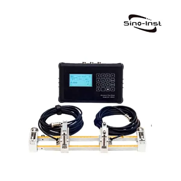
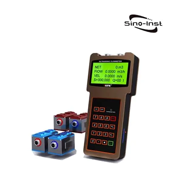
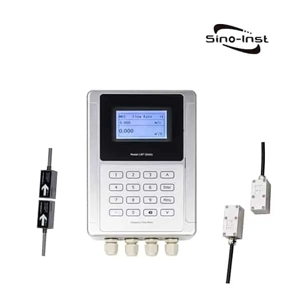
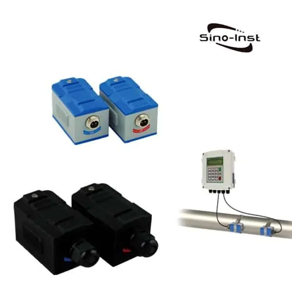
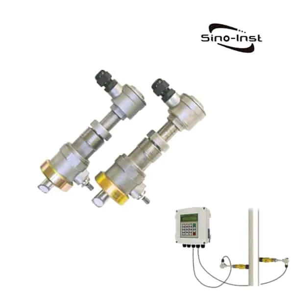
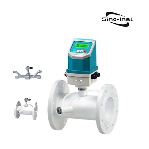
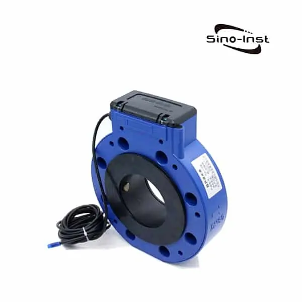
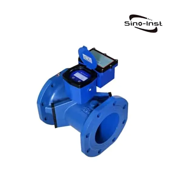
Transit Time Ultrasonic Flow Meter is a multi-channel flow meter. A velocity flow meter that measures the flow rate of the medium using the time difference method.
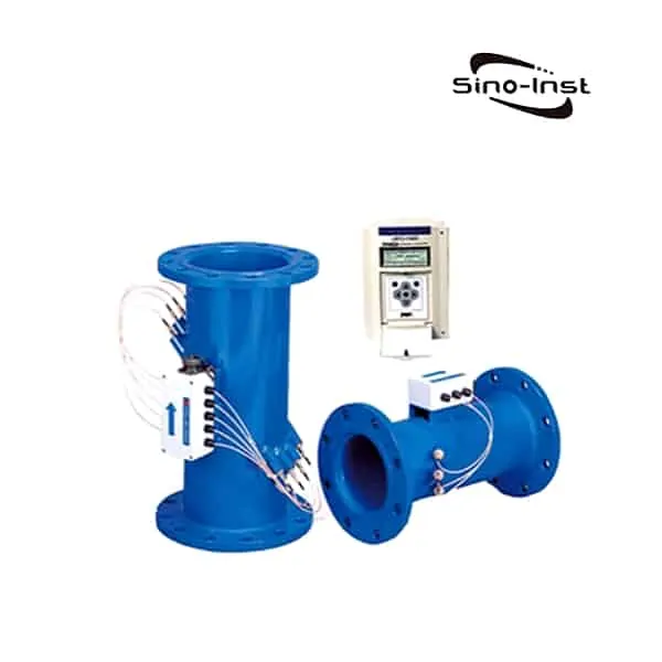
Transit Time Ultrasonic Flow Meter is the flow velocity obtained by measuring the difference in the propagation time of the ultrasonic pulse in the measured medium. When multiple beams of ultrasonic waves propagate in a flowing fluid, they carry information about the fluid velocity. The flow rate of the fluid can be detected by the received ultrasonic wave and converted into flow rate. The use of ultrasonic flowmeter eliminates the need to install measuring elements in the fluid. No additional resistance is generated.
Sino-Inst offers a variety of Ultrasonic flow meters for flow measurement. If you have any questions, please contact our sales engineers.
Features of Multipath Transit Time Ultrasonic Flow Meter
- High measurement accuracy:
- The multi-channel ultrasonic flowmeter calculates the surface average velocity and flow rate by double integration of the velocity distribution and area distribution. It is not affected by the Reynolds number during the measurement, so high accuracy and high repeatability can be obtained.
- Two-way measurement: It can measure the forward and reverse flow of the measured fluid.
- Large measuring range: The measuring range of flow velocity can reach 0.03m/s~20m/s.
- Wide application range:
- The nominal diameter of the measuring pipe can reach DN25mm~15000mm.
- The measuring width of the open channel can reach 30 m.
- The measuring width of the river can reach 150m.
- Good low flow rate:
- The multi-channel ultrasonic flowmeter can obtain high accuracy in a more complicated state with low flow rate. The problem of inaccurate measurement in the low flow rate area is solved.
- Dry-type verification technology:
- It can realize online verification, which solves the problem that large-diameter flow meters and flow meters in use cannot be verified in real flow. It also reduces the cost of verification.
- Continuous flow online installation and maintenance:
- It can be installed and maintained online to avoid the loss caused by the current cut. No need to set up bypass pipelines, reducing construction and maintenance costs.
- Low pressure loss: no drive, protruding and other obstructive parts, no pressure loss.
- Short upstream and downstream straight pipe sections required: accuracy can be guaranteed when the upstream 5D and downstream 2D (D is the pipe diameter) are met.
- Can display and transmit pressure signal:
- Install a pressure sensor to measure fluid pressure, which can be displayed on the secondary meter and realize communication.
- With RTU function:
- Can store positive and negative instantaneous flow, cumulative flow, flow rate, pressure, power failure records and other information.
- You can download and store data on-site. It can also be remotely transmitted to the upper computer for control and management.
Extended Reading: Inline Ultrasonic Flow Meter
Specifications of Multipath Transit Time Ultrasonic Flow Meter
| Number of channels | 1 | 3 | 5 | ||
| Nominal diameter (mm) | DN50~DN600 | DN80~DN600 | DN150~DN15000 | ||
| Average flow velocity (m/s) | 1.0~20 | 0.05~0.5 | 0.5~20 | 0.02~0.5 | 0.5~20 |
| level of accuracy | 0.5 | 1 | 0.5 | 0.5 | 0.25 |
| Repeatability | 0.3 | 0.3 | 0.2 | 0.15 | 0.1 |
| Environment temperature: | -20℃~ + 60℃ |
| Relative humidity of environment: | ≤ 90% |
| Medium temperature: | -20℃~+ 80℃;-40℃~+ 150℃ (optional) |
| Media status: | The measured medium should be a uniform liquid that does not affect the propagation of ultrasonic waves. |
| Fluid pressure: | PN1.0, PN1.6, PN2.5, PN4.0 (other) |
| Power supply: | AC 110V/220V±10% (50/60Hz) DC 24V±10% |
| Meter power consumption: | 18w |
| Measuring tube (one-time meter): | IP68 |
| Controller (secondary meter): | IP65 (please equip an instrument box if placed outdoors) |
| Display parameters | Instantaneous flow, cumulative flow, flow rate, time, pressure (optional) |
| Analog signal: | 4∼20mA 1. In the SOURCE active mode, the maximum load resistance is 500Ω, and the jumpers 2 and 3 on the bottom right of the main board are shorted; 2. In the case of LOOP passive mode, pins 1 and 2 are short-circuited, and an external DC24V power supply is required |
| Frequency output: | 1kHz 10kHz (optional) |
| Police report: | High value, low value (NPN-TYPE 24VDC) |
| News: | RS232/RS485 (switching) |
| Store information: | Store 2400 sets of cumulative flow/instant flow, 100 sets of switch records/error information codes, more optional. |
Guess You’ll Like: Ultrasonic flow meters types & technical guide
Transit Time Ultrasonic Flow Meter Principle
The time difference method is actually based on the vector superposition of the ultrasonic propagation velocity and the liquid velocity. It can be simply compared to the process of ferrying on a river.
Although the speed of the ferry itself is the same when flowing downstream and upstream.
However, due to the influence of the current speed, the time required for the ferry to reach the opposite bank is less when the flow is downstream than when it is upstream. The greater the flow velocity, the faster the downstream speed, and the longer the time required for the upstream flow. The time difference between the forward and reverse flow is proportional to the flow velocity.
Transit time ultrasonic flow meter equation
The difference in the upstream and downstream measurements taken over the same path is used to calculate the flow through the pipe:
V = K • D/sin2θ • 1/(T0 – t)2 ΔT
Where:
V = Mean velocity of flowing fluid
K = Constant
D = Inner diameter of the pipe
θ = Incident angle of ultrasonic waves
T0 = Zero flow transit time
ΔT = T1 – T2
T1 = Transit time of waves from upstream transmitter to downstream receiver
T2 = Transit time of waves from downstream transmitter to upstream transmitter
t = Transit time of waves through pipe wall and lining
The above equation shows that the flow velocity of the fluid is directly proportional to the difference in the upstream and downstream measurements.
The transit time ultrasonic flow meter has three possible transducer configurations: Z, V and W.
All are recognized as a single measuring path, whereas the ultrasonic beam follows a single path. In all three configurations, the output produced by the transducers is converted to a current, frequency or voltage signal. The preferred configuration is determined by factors such as:
- Pipe size
- Space available for mounting the transducers
- Condition of the internal walls of the pipe
- Type of lining
- The characteristics of the flowing liquid
In the “Z” configuration, the transducers are positioned on opposite sides of the pipe with one downstream from the other.
Usually, the distance downstream is approximately D/2, where D equals the diameter of the pipe. The optimum distance is calculated by a converter. This arrangement is only advisable under conditions where there is limited space, high turbidity, a mortar lining or a thick build-up of scale on the interior walls of the pipe. It should be avoided for installations on small pipes, where the accuracy of its measurements tends to degrade.
The “V” configuration is recommended for most installations. This arrangement places the two transducers on the same side of the pipe within approximately a diameter of the pipe from each other. A rail attachment clamps on the pipe and allows the transducers to be slid horizontally to position them the calculated distance apart.
A “W” configuration is most often used for installations on pipes with diameters of ½ inch to 1½ inches. In this arrangement, the ultrasonic signal rebounds from the wall three times; therefore, it must travel a greater distance. High turbidity liquids, and scale or deposit build-up on the interior of the pipe wall can diminish accuracy.
Extended reading: Ultrasonic flow detectors types
More Transit Time Ultrasonic Flow Meter
Sino-Inst, Manufacturer for Transit Time Ultrasonic Flow Meters. It can measure a single sound-conducting liquid medium. It can measure even liquids such as water, seawater, oil, and slurry.
Sino-Inst’s Transit Time Ultrasonic Flow Meter, made in China, Having good Quality, With better price. Our flow measurement instruments are widely used in China, India, Pakistan, the US, and other countries.

Wu Peng, born in 1980, is a highly respected and accomplished male engineer with extensive experience in the field of automation. With over 20 years of industry experience, Wu has made significant contributions to both academia and engineering projects.
Throughout his career, Wu Peng has participated in numerous national and international engineering projects. Some of his most notable projects include the development of an intelligent control system for oil refineries, the design of a cutting-edge distributed control system for petrochemical plants, and the optimization of control algorithms for natural gas pipelines.

