What Is Zirconia Oxygen Sensor?

Welcome to the world of Zirconia Oxygen Sensors, a cornerstone of precision in process control and industrial efficiency. Oxygen plays a pivotal role in numerous industrial processes, making its precise monitoring critical. That’s where our focus, the zirconia oxygen sensor, enters the scene.

What Is Zirconia Oxygen Sensor

What is zirconia oxygen sensor?

A zirconia oxygen sensor, also known as a zirconium dioxide oxygen sensor, is a type of sensor that measures oxygen levels, often used in automotive and industrial applications.

Its key differentiator? It relies on the unique properties of zirconia, or zirconium dioxide, a solid-state material known for its conductive abilities. But, let’s not get ahead of ourselves. By the end of this comprehensive guide, you’ll not only know how these sensors work but also appreciate their value in your operations.

Why zirconia oxygen sensor is important ?

In 1889, Nernst discovered the ionic conduction phenomenon of stabilized zirconia at high temperature. Since then, zirconia has become the most common solid electrolyte for research and development, and it has been widely used in high-temperature technology, especially high-temperature testing technology.

Compared with the existing oxygen measuring instruments (paramagnetic oxygen analyzer, electrochemical oxygen analyzer, etc.), the oxygen probe has simple structure, short response time (0.1s~0.2s), wide measurement range (from ppm to hundred content), high operating temperature (600°C ~ 1200°C), reliable operation, convenient installation, and small maintenance. Therefore, it is widely used in metallurgy, chemical industry, electric power, ceramics, automobiles, environmental protection and other industrial sectors.

In the kiln combustion process, when the air excess coefficient is too small, that is, the oxygen content is insufficient, the thermal efficiency decreases and black smoke is caused by the increase of incomplete combustion loss; when the oxygen content is too large, and due to the large exhaust smoke loss, SO2 And the amount of NOX increases. It will also lead to low thermal efficiency and environmental pollution.

Therefore, the use of the oxygen analyzer can automatically and continuously monitor the oxygen content in various furnace flue gases. To control the precise air-fuel ratio and achieve economical combustion, can obtain accurate thermal efficiency and reduce environmental pollution.

Oxygen analyzers do more than provide useful parameters for operators to adjust the air/fuel ratio. It can realize the automation of thermal control and achieve the purpose of energy saving and production increase.

The oxygen sensor, the core component of the oxygen analyzer, is made of stable zirconia material, and the melting point of the material is above 2200°C. It has good performance of high temperature resistance and corrosion resistance. Zirconia flue gas oxygen analyzer can adapt to high temperature, large dust and corrosive environment. It is unmatched by other methods, and it is the preferred instrument generally adopted by various countries in recent decades.

The Science Behind Zirconia Oxygen Sensors

1. Detection sensor

In this system, the detector is the most important working part. It directly affects the performance and life of the whole system.

Among them, the zirconium tube assembly is the main working device. It is the key to convert changes in oxygen concentration into changes in electrical signals.

The principle of oxygen measurement is as follows. The zirconium tube is mixed with yttrium oxide or calcium oxide in pure zirconium oxide. Stabilized zirconia sintered at high temperature, it is a solid electrolyte, generally made into a tube.

It is a good conductor of oxygen ions under high temperature conditions above 600°C.

Porous platinum (Pt) electrodes are sintered on both sides of the zirconia electrolyte (ZrO2 tube).

At a certain temperature, when the oxygen concentration on both sides of the electrolyte is different, the oxygen molecules on the high concentration side (air) are adsorbed on the platinum electrode and combine with electrons (4e) to form oxygen ions O2-. Make this electrode positively charged.

O2- ions migrate to the Pt electrode on the low oxygen concentration side through the oxygen ion vacancies in the electrolyte to release electrons and convert them into oxygen molecules, making the electrode negatively charged.

The zirconia tube becomes an oxygen concentration battery.

The following reaction will take place at the two platinum electrodes:

On the air side (reference side) electrode: O2+4e → 2O2-
On the hypoxic side (measured side) electrode: 2O2-→ O2+4e

That is, one oxygen molecule in the air captures four electrons on the electrode and becomes two oxygen ions. Oxygen ions migrate through zirconia to the low-oxygen side electrode driven by the potential difference in oxygen concentration. Four electrons are left to the electrode to recombine into oxygen molecules. When the battery is in equilibrium, the potential value E between the two electrodes remains constant.

Its potential value E conforms to the Nernst equation:

In the formula:
R——gas constant
T——absolute temperature
F – Faraday constant
Px——the percentage of oxygen concentration in the measured gas
Pa – the percentage of oxygen concentration in the reference gas, generally 20.60%;

In this way, if the oxygen cell is heated to a specified temperature, the measured gas and the reference gas flow through the two sides of the zirconium tube respectively, and the potential generated has a certain relationship with their concentrations. If the concentration of the reference gas is known, it is easy to determine the oxygen concentration of the measured gas.

The detector uses this principle to provide the conditions for the normal operation of the zirconium tube to achieve practical purposes.

2. Transmitter

The function of the oxygen transmitter is to convert the oxygen potential signal and temperature signal of the detector into oxygen content according to the Nernst formula, and to control the working temperature of the zirconium tube.
Summarized into temperature measurement, temperature control, oxygen conversion, output and other functions. Different kinds of transmitters are functionally identical.

Harnessing Zirconia’s Power: Industrial Applications

Industries worldwide have recognized the value of zirconia oxygen sensors. From combustion control in power plants to maintaining the optimal environment in kilns, zirconia oxygen sensors are instrumental in ensuring operations run smoothly and efficiently.

Let’s dive into some specific industrial applications where these sensors excel.

  1. Power Plants: Power plants, particularly those burning fossil fuels, need to closely monitor and control combustion processes to maximize efficiency and minimize emissions. Here, zirconia oxygen sensors offer an accurate and durable solution.
  2. Automotive Industry: Car engines use zirconia oxygen sensors (often located in the exhaust pipe) to measure the amount of oxygen in the exhaust gas. This data is crucial for the engine control unit (ECU) to adjust the air-fuel mixture and optimize engine performance.
  3. Food and Beverage Industry: In food packaging, zirconia oxygen sensors are used to monitor oxygen levels and ensure the longevity and quality of the product.

Our Recommended Zirconia Oxygen Sensors

DisplayLCD menu operation
Instrument accuracy1%
Temperature control accuracy±1℃
output4-20mA
power supply220V+10%
power<150W
Range0-25% (programmable)
Flue gas temperature0-700℃
Flue gas pressure-20KPa~+20KPa
Protection tube material316L stainless steel protection tube
SpecificationΦ45mm
Transmitter materialcast aluminum
degree of protectionIP65
flangeOuter diameter 155mm hole distance 130mm (other specifications are optional)
Furnace resistance valueStandard 60Ω (optional 80Ω, 120Ω, 160Ω)
service life15 years (according to actual working conditions)
Probe length500mm, 800mm, 1000mm, 1200m (other specifications can be customized)

Selection of Zirconia Oxygen Analyzer/zirconia oxygen sensor

Low temperature type is selected when the flue gas temperature is below 400°C;
When the flue gas temperature is below 700°C, select the warm type;
Choose the high temperature type when the temperature is above 700°C.
If the flue gas contains more corrosive gases, an aspirating oxygen analyzer with a sample gas pretreatment device should be selected.

The total length of the probe refers to the length from the installation flange to the sampling port of the oxygen sensor. The actual total length of the probe will also add 150mm to the length of the junction box.
Probe length = mounting screw distance 100mm + furnace wall thickness + length inserted into the furnace or flue (generally around 400mm)

Oxygen converters can be divided into disc meters and wall meters according to the installation form. Disc watches include a disc vertical watch and a disc horizontal watch.
The installation position of the wall-mounted meter can be selected at a place close to the oxygen detector and convenient for debugging.

There are four options for the oxygen content of the full scale of the transmitter: 0~5%, 0~10%, 0~20.6% (factory default value), 0~25%. Corresponding to the current output 4 ~ 20mA.

More Gas Measurement Solutions

Digital air flow meters

What Is Digital Air Flow Meters? The digital air flow meter is also a digital gas flow meter. The digital…

Industrial CO2 flow meters

CO2 flow meters are instruments that can measure the flow of gaseous or liquid carbon dioxide. CO2 is a common…

Industrial Oxygen Flow Meters

Oxygen Flow Meters are digital flow meters that can measure industrial oxygen. It is very important to choose a suitable…

As a seasoned manufacturer and supplier, we take pride in offering a broad range of top-tier zirconia oxygen sensors. However, we understand that every business is unique. That’s why we go above and beyond to provide customized solutions, specifically tailored to your distinct operational needs.

At Sino-Inst, we’re not just providers; we’re partners in your operational success. With our high-quality, customizable zirconia oxygen sensors, you gain accuracy, reliability, and the edge you need in your industry. Our experienced team is ready to help tailor solutions that fit your specific needs. Elevate your operations with us— reach out to Sino-Inst today. Choose excellence. Choose partnership. Choose Sino-Inst.

Request a Quote

Please enable JavaScript in your browser to submit the form

Integrated Zirconia Oxygen Analyzer

Zirconia Oxygen Analyzer is an analyzer used to monitor and control the oxygen concentration of flue gas in combustion gases, boilers and industrial furnaces. Widely used in industrial fields that require a lot of energy – such as steel plants, power plants, petroleum and petrochemical, ceramics, paper, food or textile industries, as well as various incinerators and medium/small boilers, etc. Zirconia Oxygen Analyzer helps save energy. It can also reduce CO2, SOx, and NOx emissions by controlling complete combustion. Contribute to the protection of the earth’s environment, prevention of global warming and air pollution.

Integrated Zirconia Oxygen Analyzer Features

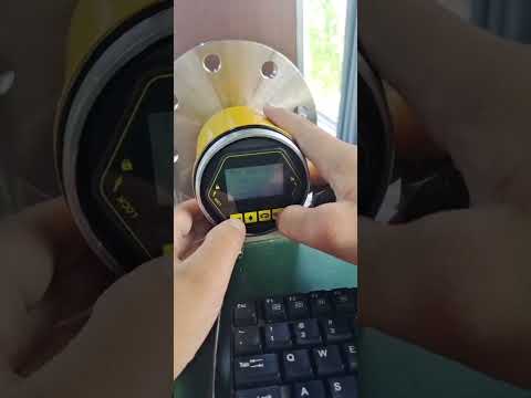
  • Aluminum die-casting junction box, IP65 protection level, exquisite appearance.
  • The filter adopts a circular sheet shape, which reduces the direct erosion of flue gas and prolongs the service life.
  • At the same time, there is no need to consider the directionality.

Technical Specifications

DisplayLCD menu operation
Instrument accuracy1%
Temperature control accuracy±1℃
output4-20mA
power supply220V+10%
power<150W
Range0-25% (programmable)
Flue gas temperature0-700℃
Flue gas pressure-20KPa~+20KPa
Protection tube material316L stainless steel protection tube
SpecificationΦ45mm
Transmitter materialcast aluminum
degree of protectionIP65
flangeOuter diameter 155mm hole distance 130mm (other specifications are optional)
Furnace resistance valueStandard 60Ω (optional 80Ω, 120Ω, 160Ω)
service life15 years (according to actual working conditions)
Probe length500mm, 800mm, 1000mm, 1200m (other specifications can be customized)

Frequently Asked Questions

Zirconia oxygen analysis is a method of measuring the oxygen content in a gas sample. The technology is based on the fact that zirconium dioxide, or zirconia, is an oxygen ion conductor at high temperatures. When a voltage is applied across a zirconia cell, it drives oxygen ions from one side to the other, creating a current proportional to the oxygen concentration in the gas sample. This technology is widely used in a variety of industries, including combustion control systems, car emission controls, and environmental monitoring.

A zirconia oxygen analyzer usually operates at a high temperature, typically around 700 to 800 degrees Celsius. At these elevated temperatures, zirconia becomes a good conductor of oxygen ions. This high temperature is crucial for the operation of the device, as it facilitates the necessary electrochemical reactions that allow oxygen ions to move across the zirconia membrane, generating an electrical signal proportional to the concentration of oxygen.

The operation of a zirconia oxygen analyzer is based on the Nernst equation. This equation expresses the relationship between the voltage generated across a zirconia cell and the oxygen concentrations on each side of the cell. Here it is in its simplest form:

E = E0 + RT/4F * ln(pO2(1)/pO2(2))

Where:

E is the voltage across the cell,
E0 is the standard cell potential,
R is the gas constant,
T is the temperature in Kelvin,
F is Faraday’s constant,
pO2(1) and pO2(2) are the partial pressures of oxygen on the two sides of the cell.

Zirconia and titania O2 sensors both serve the same purpose of measuring oxygen levels, but they operate using different principles and have different characteristics:

Zirconia sensors rely on the Nernst effect, which creates a voltage difference proportional to the logarithm of the oxygen pressure difference across a zirconia cell. Zirconia sensors are excellent at providing accurate and reliable measurements and are commonly used in automobile exhaust systems and industrial applications.

Titania sensors, on the other hand, change their electrical resistance according to the concentration of oxygen. When exposed to a rich mixture (more fuel, less oxygen), the resistance of the titania sensor increases; when exposed to a lean mixture (less fuel, more oxygen), the resistance decreases. This type of sensor is simpler and more robust but provides less precise measurements compared to zirconia sensors.

Standard gas:

National secondary standard material, oxygen in nitrogen. Oxygen content is proportioned according to need. The general standard is 5.0%. Calibrate zirconia oxygen analyzers against known gas standards. Turn on the calibration gas, connect the calibration gas connection hose to the calibration gas inlet of the zirconia probe, and judge whether the zirconia oxygen analyzer is accurate according to the known oxygen content of the calibration gas.

Selection of Zirconia Oxygen Analyzer

1) The flue gas temperature at the recommended installation sampling point

Low temperature type is selected when the flue gas temperature is below 400°C;
When the flue gas temperature is below 700°C, select the warm type;
Choose the high temperature type when the temperature is above 700°C.
If the flue gas contains more corrosive gases, an aspirating oxygen analyzer with a sample gas pretreatment device should be selected.

2) Select the probe length

The total length of the probe refers to the length from the installation flange to the sampling port of the oxygen sensor. The actual total length of the probe should also add 150mm to the length of the junction box.

Probe length = mounting screw distance 100mm + furnace wall thickness + length inserted into the furnace or flue (generally around 400mm)

3) Instrument selection

Oxygen converters can be divided into disc meters and wall-mounted meters according to the installation form. The disc meters include disc vertical meters and disc horizontal meters. The installation position of the wall-mounted meter can be selected at a place close to the oxygen detector and convenient for debugging.

There are four options for the oxygen content of the full scale of the transmitter: 0~5%, 0~10%, 0~20.6% (factory default value), 0~25%, corresponding to the current output of 4~20mA.

More Gas Measurement Solutions

Introducing our Integrated Zirconia Oxygen Analyzer, a cutting-edge tool designed to measure oxygen levels accurately. This device utilizes zirconia’s unique properties to give precise readings in various environments, from car emissions control to environmental monitoring.

We, at Sino-Inst, are experienced manufacturers and suppliers in the field of Zirconia Oxygen Analyzers. We not only offer top-quality products but also provide customization to cater to your unique needs. With Sino-Inst, you get a reliable partner committed to your success.

Contact us today to discover how our Integrated Zirconia Oxygen Analyzer can enhance your operations.

Request a Quote

Please enable JavaScript in your browser to submit the form

Grain Bin Level Indicators: The Missing Piece in Your Grain Storage Solution

Grain Bin Level Indicators are transformative tools for modern agriculture. They give accurate, real-time measurements to prevent bins from being overfilled or underfilled.
Revolutionizing grain management, these devices facilitate accurate real-time grain bin measurements, mitigating the risk of overfilling or underfilling.
They’re the real game-changers in grain storage solutions. Perfect for maintaining optimal grain storage conditions, these indicators are truly the unsung heroes in grain storage solutions.

The Challenges of Grain Storage

Grain storage, especially in large-scale silos for processing, presents a number of challenges:

  • Maintaining Optimal Storage Conditions: This is crucial for preserving grain quality and preventing spoilage.
  • Monitoring Levels: Ensuring bins are neither overfilled nor underfilled is necessary to avoid waste and maintain operational efficiency.
  • Managing Large Quantities: Industrial silos often contain vast quantities of grain, making it difficult to monitor levels accurately.
  • Ensuring Safety: Overfilled or underfilled bins can lead to safety issues, like structural damage to the silos or poor grain circulation leading to spoilage.
  • Protecting Profits: All of these challenges, if not managed effectively, could lead to inefficiencies, increased costs, and reduced profits.

The Grain Bin Level Indicator offers a solution to these issues, helping to improve the grain storage and processing system.

Grain Bin Level Indicator: A Game-Changer in Grain Storage

The Grain Bin Level Indicator is a technological marvel in grain storage management. This device provides real-time level monitoring, sending alerts when the grain reaches a specified level. No more guesswork, no more wasting hours manually checking levels.

Not convinced yet? Let’s dig a little deeper into the workings and benefits of this amazing product.

Grain Bin Level Indicators, also known as level sensors, come in different varieties to suit various applications. Here’s an overview of some common types and their working principles:

These sensors work based on the principle of capacitance. They measure changes in an electrical field to determine the level of grain in the bin.

Rotary level indicators are mechanical devices that have a rotating paddle. When the paddle encounters resistance from the grain, it stops rotating. This stoppage triggers a signal that indicates the level of grain in the bin.

These sensors use sound waves to determine the level of grain. An ultrasonic pulse is emitted from the sensor, which then waits for the pulse to bounce back after hitting the surface of the grain. The time it takes for the pulse to return helps determine the level of grain in the bin.

Similar to ultrasonic sensors, radar level sensors also use wave technology. However, instead of sound waves, they utilize radio waves, which can be more accurate in certain conditions.

These sensors vibrate at a certain frequency when there’s no grain present. When grain reaches the level of the sensor and dampens its vibration, it sends a signal indicating the grain level.

Type of SensorWorking PrincipleAdvantagesLimitations
Capacitance Level SensorsMeasures changes in an electrical field to determine grain levelReliable and accurate, suited to a variety of grainsMay require calibration for different types of grain
Rotary Level IndicatorsUses a rotating paddle that, when obstructed by grain, stops and sends a level signalSimple and cost-effectiveMechanical parts may wear out over time
Ultrasonic Level SensorsUses sound waves; the time for a pulse to bounce back indicates the grain levelAccurate, no moving parts, suitable for large binsCan be affected by dust and other atmospheric conditions
Radar Level SensorsUses radio waves; like ultrasonic sensors, measures the time for a pulse to returnVery accurate, not as affected by atmospheric conditions as ultrasonic sensorsCan be more expensive than other options
Vibrating Rod Level SensorsVibrates at a certain frequency; when grain dampens the vibration, it sends a level signalReliable and accurate, simple to install and useMay not be suitable for extremely light or fluffy grains

It’s important to note that different types of grain bin level indicators are suited to different applications and types of grains. Choosing the right one depends on your specific needs and circumstances. For more details about these indicators, their advantages, and how they can be integrated into your grain storage system, feel free to contact our team at Sino-Inst.

Unveiling the Power of Grain Bin Level Indicators

To appreciate the power of grain bin level indicators, consider this: A study by Purdue University revealed that grain spoilage and mishandling account for over $2.5 billion in losses annually in the US alone. This is where grain bin level indicators can make a real difference.

By providing accurate, real-time level data, these devices can prevent overfilling, reduce spoilage, and ultimately increase profitability. Moreover, grain bin level indicators are versatile, easy to install, and can be integrated into existing storage management systems.

Remote Level monitoring

It is necessary to realize the remote transmission display of the granary material level. There are three possible ways.

  1. Add a split monitor. General level meter as for a local display. But a monitor can be added if desired. Level meter mounted on top of tank with local display. A second display is mounted on the bottom of the tank. It is convenient for the staff to check the level and debug.
  2. Signal output. A general level meter can support 4-20mA or RS485 signal output. The output signal can be wired to the control room. Monitoring software for connection to PLC, DCS or user.
  3. Wireless IoT. With the addition of accessories such as a wireless gateway, the level meter can output the level signal through a wireless signal for a long distance. Such as GPRS, 4G, LoRA, etc.

FAQ

The Saf T fill grain bin level indicator is a popular model of level indicators designed for grain bins. It offers a simple, reliable way to prevent overfilling of grain bins.

Traditionally, grains in a grain bin are measured using a manual method known as ‘taping’. However, this method can be inaccurate and time-consuming. Modern methods include using devices like grain bin level indicators, which provide real-time, accurate measurements.

A bin level measuring system is a technology used to monitor and control the level of materials like grains in storage bins. These systems provide real-time data, helping to prevent overfilling or underfilling.

The number of bushels in a bin can be calculated using the bin’s diameter and height, and the type of grain stored. However, for more accurate measurements, devices like grain bin level indicators are recommended.

More Tank Level Measurement Solutions

In conclusion, grain bin level indicators are the missing piece in your grain storage solution. These devices, though small and simple, can revolutionize the way you manage your grain storage, saving you time, money, and unnecessary stress.

At Sino-Inst, we are a trusted manufacturer and supplier with years of experience in providing solutions to farming challenges. Our grain bin level indicators are customizable to suit your specific needs. Contact us today to discover how our products can transform your farming operations.

Request a Quote

Please enable JavaScript in your browser to submit the form

Gas Detection

Explore our wide range of gas detectors designed for numerous applications. We offer devices to detect individual gases like oxygen, carbon monoxide, and more, ensuring safety and efficiency. Choose from portable to fixed detectors or even multi-gas variants for diverse needs. We also provide alarm systems and water quality detectors. Simplify your safety and compliance needs with our easy-to-use, reliable instruments.

Gas Detection Products

More Detection and Analysis Sloutions

Request a Quote

Please enable JavaScript in your browser to submit the form

Voltage Pressure Transducer Comparison

Imagine being in a world where pressure measurements are a hassle. You’re constantly struggling with inaccurate readings, device malfunctions, and complicated setup processes. Sounds exhausting, right? Now enter voltage pressure transducers. These little devices are the unsung heroes of the industrial world, transforming your pressure measurement process from a frustrating chore into a smooth, reliable operation. Let’s dive in and learn more about these game-changing tools.

What is a Voltage Pressure Transducer?

A voltage pressure transducer is an electromechanical device that converts pressure into an analog voltage signal. This signal can be easily read and analyzed, making pressure monitoring a breeze. But how does it all work? Let’s find out.

More detailed guide about pressure transducers here:

The Inner Workings of Voltage Pressure Transducers

At the heart of every voltage pressure transducer is a sensing element, often a strain gauge or a piezoresistive sensor. When pressure is applied, this element deforms slightly. This deformation alters the electrical resistance of the sensor, and this change is converted into a voltage signal proportional to the applied pressure.

Voltage pressure transducers come in a variety of types, each suited to specific applications. Some popular types include strain-gauge pressure transducers, piezoresistive pressure transducers, and capacitive pressure transducers.

Why Voltage Output Signals?

Pressure changes can trigger variations in a sensor’s electrical resistance. In voltage output transducers, these changes convert into a voltage signal that matches the shift in pressure. These voltage signals usually fall within 0-5Vdc or 0-10Vdc, although the range can vary depending on the transducer and its application.

Voltage output signals, common in pressure and temperature sensors, are a type of analog output signal. There are many output options to choose from in this category. The most frequently seen ones in industrial settings are 1-5VDC, 1-6VDC, and 0-10VDC, particularly when power usage isn’t a main concern.

In our growing world of IoT and IIoT, sensors can now run on low power while using less current. This is a big win for remote equipment where replacing batteries often can be expensive and time-consuming.

In response to the demand for low power, various voltage output choices now run on 3V, 3.3V, 3.7V, 5V, and 9V power supplies and batteries. Some common signal pairings with these supply voltages include millivolt, 0.5-2.5VDC non-ratiometric, and 0.5-4.5VDC ratiometric outputs. The 0.5-2.5VDC output option is becoming more popular due to increased usage of 3 to 5VDC lithium-ion batteries.

While millivolt signals are ratiometric, 0.5-4.5VDC output, ratiometric to a regulated 5VDC excitation, is more commonly associated with the term “ratiometric.” This type of signal has gained popularity in automotive and off-road applications because it is proportional to the supply. For instance, a 10% drop in supply from the 5V source would result in a 10% decrease in the output signal. This type of signal continues to be used in similar applications and has also found use in industrial applications like compressors and water pumps.

Voltage Output Wiring Configurations

Voltage output pressure transducers typically come in two wiring configurations: three-wire and four-wire systems.

In a three-wire system, one wire is connected to the positive voltage supply, another to the output, and the third one to the ground. This setup is straightforward and commonly used.

The four-wire system, on the other hand, uses two wires for the supply voltage and two wires for the output. This configuration reduces errors due to voltage drop in the supply leads, providing more accurate readings, especially over longer distances.

Our Top Voltage Pressure Transducer Picks

Applications of Voltage Output Pressure Transducers

  1. Tank Level Monitoring: Paired with a SCADA system, these sensors are ideal for remotely monitoring fuel or water levels, especially in locations where conserving battery life is essential.
  2. Oil Field Equipment: In far-flung oilfields, these sensors help conserve battery life while providing ample signal strength for measuring and transmitting data to telemetry units and then to the cloud.
  3. Industrial Internet of Things (IIoT): Factories are increasingly adopting IoT technology to measure pressure and temperatures of various equipment, particularly where installing power sources is costly or difficult.
  4. HVAC and Refrigeration: For HVAC/R installations, these affordable, user-friendly sensors swiftly provide pressure, temperature, and combined readings, making them popular for use in confined spaces like boiler rooms.
  5. Automotive Systems: In vehicles, these sensors are crucial for monitoring systems like brakes and fuel, delivering real-time data for optimal operation.
  6. Aerospace and Aviation: These sensors offer real-time measurements in critical monitoring areas such as cabin pressure, engine oil pressure, and hydraulic systems, ensuring safe and efficient flights.

FAQ

A voltage pressure transducer is a device that converts pressure into a voltage signal, enabling easy monitoring and control of pressure.

The input voltage of a pressure transducer, also known as the excitation voltage, typically ranges from 5 to 36 volts DC, but it varies by model. Always refer to the manufacturer’s specifications.

To check the voltage on a pressure transducer, you’ll need a digital multimeter. Attach the multimeter’s probes to the transducer’s output wires and apply pressure. The multimeter should display the corresponding voltage.

A 4-20mA pressure transducer is a type of pressure transducer that outputs a current signal instead of a voltage signal. The 4-20mA signal is less susceptible to electrical noise, making it ideal for long-distance signal transmission.

Voltage output signals in pressure transducers play a crucial role in pressure monitoring and control. Understanding the workings of these signals and their appropriate applications can help you choose the right transducer for your specific needs.

Remember, at Sino-Inst, we offer a variety of voltage pressure transducers tailored to your requirements. Our experienced team is ready to assist you in finding the best pressure measurement solutions. Reach out to us today!

Request a Quote

Please enable JavaScript in your browser to submit the form

Secrets of Shaft Torque Sensors: All You Need to Know

Torque sensors are essential components in many mechanical systems. They measure the torque, or rotational force, applied to a rotating system such as a motor, crankshaft, gearbox, or capstan. In essence, the torque sensor is like the heartbeat monitor of a machine, providing critical performance data.

But let’s focus on one type in particular: the shaft torque sensor. These unique sensors directly measure the torque on a rotating shaft. Providing real-time, highly accurate measurements crucial for monitoring and control applications.

Characteristics of Shaft Torque Sensors

  • Direct Measurement: Shaft torque sensors measure torque directly on the rotating shaft. This means they provide real-time data which is crucial for monitoring and controlling systems.
  • High Accuracy: These sensors are known for their high precision, delivering reliable data for various applications.
  • Wide Range: Shaft torque sensors can measure a wide range of torques. Making them versatile for different needs.
  • Rugged and Durable: Designed to withstand the harsh conditions of a rotating shaft. These sensors are typically rugged and durable. Ensuring they deliver accurate results over time.
  • Compact Size: Many shaft torque sensors are compact, which allows them to be installed in areas with limited space.
  • Easy Integration: These sensors can often be easily integrated into existing systems, saving time and resources in setup.

Remember, these are general characteristics. Specific features can vary depending on the particular model or manufacturer.

At Sino-Inst, we offer a variety of shaft torque sensors, each with their own unique benefits, to ensure you get the perfect fit for your specific needs.

Featured Torque Sensors

Where are Shaft Torque Sensors Used? Real-World Applications

Automotive Industry:

Shaft torque sensors play an integral role in the automotive sector. They are extensively used to measure engine output, drivetrain performance, and for electric power steering systems. Accurate torque measurements can lead to improvements in the vehicle’s fuel efficiency and overall performance.

Manufacturing and Assembly Lines:

Shaft torque sensors are vital in automated assembly systems, including manufacturing of appliances, electronics, and automobiles. They ensure that screws, bolts, and other fasteners are tightened with the correct amount of torque, thereby maintaining the quality and integrity of the product.

Renewable Energy:

In wind turbines, shaft torque sensors measure the power output, helping in efficient power generation and early detection of system failures. This contributes to the reliability and longevity of these renewable energy systems.

Aerospace:

Shaft torque sensors are used in the testing and maintenance of aircraft engines and components. They provide valuable data to ensure the efficiency and safety of the aircraft.

Maritime Applications:

In the maritime industry, shaft torque sensors are used to monitor the performance of ship propellers, optimizing fuel consumption, and diagnosing potential issues.

These examples are based on general knowledge and industry practices. At Sino-Inst, we can offer tailored solutions and consultations to meet your specific needs.

Choosing the Perfect Shaft Torque Sensor: Key Factors to Consider

Absolutely, selecting the ideal shaft torque sensor involves many considerations to ensure it performs well in its intended application. Here are some of the key factors you should take into account:

  1. Measurement Range: The sensor should have the capacity to measure the maximum torque that will be applied to the shaft without going beyond its limit.
  2. Accuracy: Consider the sensor’s accuracy and resolution. You want a sensor that can measure torque with the degree of precision required for your specific application.
  3. Installation Requirements: Make sure the sensor can be installed onto your existing shaft without requiring significant modifications to your machinery.
  4. Environment: The sensor should be able to withstand the environmental conditions it will be exposed to, such as temperature, humidity, vibration, and dust.
  5. Output Signal: Depending on your system, you might need a sensor with a specific type of output signal (analog, digital, wireless, etc.).
  6. Size and Weight: The sensor’s size and weight might be a crucial factor, particularly in applications where space is limited or in dynamic applications where the sensor’s weight could influence the measurement.
  7. Cost: Last but not least, consider the cost of the sensor and whether it fits within your budget.

These considerations can guide you in selecting the right shaft torque sensor for your specific needs. Remember, the best sensor is not always the most expensive one, but the one that is most suited to your application and environment.

Maintaining Your Shaft Torque Sensor

Maintaining your shaft torque sensor is crucial to ensure its longevity and performance. Here are some essential tips to help you get the most out of your sensor:

  • Regular Inspection: Conduct periodic inspections to check for signs of wear, corrosion, or damage. Look for physical signs such as cracks or deformation.
  • Cleanliness: Keep the sensor clean and free from dust or grime which can interfere with accurate readings. Use a soft cloth or air duster for routine cleaning. Avoid abrasive materials that could scratch or damage the sensor.
  • Avoid Overloading: Do not exceed the sensor’s maximum load capacity. Overloading can lead to permanent damage, resulting in inaccurate readings or total sensor failure.
  • Handle with Care: Even though most sensors are designed to withstand harsh conditions, they should still be handled with care. Avoid dropping or impacting the sensor.
  • Proper Installation: Ensure the sensor is installed correctly according to the manufacturer’s instructions. Improper installation can lead to inaccurate readings and premature sensor wear.
  • Calibration: Regular calibration is essential to ensure your sensor continues to provide accurate readings. Refer to your sensor’s manual or consult with the manufacturer for specific calibration procedures.
  • Seek Professional Assistance: If you suspect that the sensor is not working correctly, seek professional assistance. Trying to fix the problem yourself may cause further damage.

By following these tips, you can maximize the lifespan and performance of your shaft torque sensor, ultimately saving time and resources in the long run.

FAQ

A shaft torque sensor is a device that measures the torque on a rotating system like a motor, crankshaft, or gear. It provides real-time, highly accurate measurements, which are crucial for monitoring and control applications.

Torque on a shaft can be measured using a shaft torque sensor. These sensors are installed directly on the rotating shaft, where they detect and measure the torsional strain (twisting) on the shaft as it rotates under load.

In cars, a torque sensor is typically used to measure engine output torque. This information can be used to optimize engine performance, enhance fuel efficiency, and inform decisions on safety systems.

The two main types of torque sensors are static torque sensors and dynamic torque sensors. Static torque sensors measure torque without rotation (static conditions), while dynamic torque sensors measure torque during rotation.

More Torque Measurement Solutions

Shaft torque sensors are remarkable devices that play a critical role in many industries. By understanding how they work and choosing the right one for your needs, you can greatly enhance the efficiency, safety, and reliability of your operations.

At Sino-Inst, we offer a range of high-quality, customizable shaft torque sensors. As experienced manufacturers and suppliers, we’re here to help you find the perfect solution to meet your needs. Contact us to learn more about how our products can enhance your operations.

Request a Quote

Please enable JavaScript in your browser to submit the form

What Is a Differential Pressure Sensor?

What is a Differential Pressure Sensor?

A differential pressure sensor is a special instrument used to measure the pressure difference between two points in a system. It contains important parts like diaphragms, strain gauges, or capacitive elements. These sensors come in different types, such as diaphragm-based, piezoresistive, and capacitive. Each with its own benefits and uses. Unlike regular pressure sensors that measure absolute or gauge pressure, differential pressure sensors specifically concentrate on the pressure difference between two points.

Differential pressure sensors are more than just another piece of machinery; they are the eyes and ears of many industrial systems, diligently measuring the pressure difference between two points in a process. By doing this, they provide invaluable insights that keep systems operating smoothly and safely. Whether in HVAC systems, medical devices, or industrial processes, these sensors are everywhere, silently playing their part.

So, why should you care about these sensors? Let’s dive deeper.

types of differential pressure sensors

Here are some common types of differential pressure sensors:

  • Resistive Differential Pressure Sensors: These sensors use changes in resistance to measure pressure differences.
  • Capacitive Differential Pressure Sensors: These sensors utilize changes in capacitance to detect pressure variations.
  • Piezoelectric Differential Pressure Sensors: These sensors convert pressure changes into electrical signals using piezoelectric materials.
  • Optical Differential Pressure Sensors: These sensors employ optical principles to measure pressure differences.
  • Microelectromechanical Systems (MEMS): These sensors utilize miniature mechanical structures to detect and measure pressure changes.

These different types of sensors offer various advantages and are used in a wide range of applications.

Working Principles of Differential Pressure Sensors

Typically, the two pressures to be measured are applied to opposite sides of a single diaphragm. The deflection of the diaphragm, whether positive or negative, determines the pressure differential.

Diaphragm-based sensors use the deformation of the diaphragm to detect differential pressure. Whereas piezoresistive sensors use strain gauges that change electrical resistance under pressure. Capacitive differential pressure sensors measure the change in capacitance caused by a pressure difference. These conversion mechanisms enable accurate and reliable measurement of differential pressure.

Some industrial differential pressure sensors use two separate absolute sensors with internal electronics to calculate and provide differential pressure.

Another way to achieve differential pressure measurement is to use two absolute pressure sensors and then calculate the difference on the industrial control system.

This is useful in situations where two different types of sensors are required due to the measured medium (i.e. liquid and gas) or the measurement environment.

The principle of differential pressure measurement states that differential pressure (also shown as DP or Δp) is the difference between two applied pressures.

For example, if the pressure at point A equals 100psi and the pressure at point B equals 60psi, the differential pressure is 40psi (100psi – 60psi).

Read more about: Different Types of Pressure: Absolute, Gauge, Sealed Gauge and Differential Pressure

Featured Industrial Differential pressure Transmitters

Extended Diaphragm Seal DP Level Transmitter
Extended Diaphragm Seal DP Transmitter is a level transmitter direct mounted on pipe or tank. The isolation diaphragm is in direct contact with the liquid medium.
Flange Mounted Differential Pressure Transmitter
Flange Mounted Differential Pressure Transmitter is also called single flange DP level transmitter. For liquid, gas or vapor pressure measurement.
Smart Differential Pressure Transmitter
Smart Differential Pressure Transmitter measures industrial differential pressure. Can Works with diaphragm seals, capillary, HART. Outputs standard signals (such as 4 ~ 20mA, 0 ~ 5V).
Piezoresistive Differential Pressure Transmitter
Piezoresistive Differential Pressure Transmitter utilizes the piezoresistive effect of semiconductor silicon materials. Realize accurate measurement of differential pressure.
Remote Seal Differential Pressure Transmitter
Remote Seal DP Transmitter is often used as a tank level transmitter. The smart pressure transmitter is connected with a stainless steel flange by capillary. The pressure is sensed by a remote transmission device installed on a pipe or container. 
Differential pressure(DP) level transmitter
Differential pressure (DP) level transmitter is a perfect solution for tank level measurement. Flanges, seal diaphragms, capillaries, and DP transmitter are often used to measure liquid levels.
Differential Pressure Gauge
Quickly measure the positive, negative or DP of air or non-corrosive gas. Sino-Inst supplies Differential Pressure Gauges made in China. DWYER 2000 Differential Pressure Gauges, Magnehelic differential pressure gauges are also available.

Differential Pressure Sensors Vs. Pressure Sensors

When it comes to the world of pressure measurement, two types of sensors often come into focus: differential pressure sensors and pressure sensors. Both have significant roles in various industries. But they serve different functions and have unique characteristics. Let’s dive into the key differences between them.

Pressure Sensor: A pressure sensor measures the absolute pressure applied on it. It takes one pressure reading, typically against a vacuum (zero pressure). This method is similar to how we might measure the weight of an object or the temperature of a room.

Differential Pressure Sensor: A differential pressure sensor, on the other hand, measures the difference in pressure between two points. Imagine having a scale that measures the weight difference between two objects rather than the absolute weight. That’s the kind of measurement a differential pressure sensor does.

Pressure Sensor: These sensors are often used when you need to measure the overall pressure level in a system, such as barometric pressure in weather forecasting, tire pressure in vehicles, or blood pressure in medical monitoring.

Differential Pressure Sensor: Differential pressure sensors are used in applications where the pressure difference matters, such as across a filter in an HVAC system to determine when the filter needs to be replaced, or in fluid dynamics to calculate the flow rate based on pressure drop across a restriction.

Pressure Sensor: Typically, pressure sensors are simpler and less expensive than differential pressure sensors. They can be ideal for applications that don’t require the added complexity of differential pressure measurement.

Differential Pressure Sensor: These sensors are typically more complex and may cost more due to the added intricacy of measuring pressure at two points. However, they provide more detailed information, which can be crucial for certain applications.

In conclusion, while both types of sensors serve to measure pressure, the choice between a pressure sensor and a differential pressure sensor depends largely on the specific application and requirements. Understanding these differences is the first step in determining which sensor is the most suitable for your needs.

Applications of Differential Pressure Sensors

The versatility and precision of differential pressure sensors make them highly valuable in a variety of industries. Here are 6 key ones, explained in the simplest terms:

  1. HVAC Systems: These sensors help control how much air is moving in heating and air conditioning systems. They also tell us when to change filters by measuring the pressure drop across them.
  2. Industrial Control: In factories and plants, these sensors help manage the flow of chemicals, oil, gas, food and drink by monitoring pressure changes in pipes.
  3. Flow Measurement: By checking the pressure drop across a blockage in a pipe, these sensors can tell how fast a liquid or gas is flowing. More about DP flow meters.
  4. Filter Monitoring: The sensors can tell when a filter is getting clogged by noticing a change in pressure across it. This helps in timely cleaning or replacing the filter.
  5. Medical Equipment: In devices like breathing machines and infusion pumps, these sensors help control the flow of air or medication to ensure the patient’s comfort.
  6. Tank Level Measurement: By measuring the pressure difference from the top to the bottom of a tank, these sensors can accurately tell how full a tank is, be it water, fuel, or grains. More about: Use Differential Pressure Transmitter to Measure Liquid Level.

In a nutshell, from air conditioning systems to medicine, and fuel storage to food factories, differential pressure sensors make things work better and safer. They are truly a vital part of many systems and processes.

FAQ

A differential pressure sensor measures the pressure difference between two points within a system. This information can be used to control or monitor a process.

A pressure sensor measures the force exerted by a fluid on a surface, while a differential pressure sensor measures the difference in pressure between two points.

In air applications, a differential pressure sensor can be used to monitor and control airflow in HVAC systems or to monitor the status of filters.

Yes, a differential pressure sensor is a type of transducer as it converts pressure into an electrical signal.

The main purpose of a differential pressure sensor is to measure the difference in pressure between two points within a system. This information is vital in many applications, from HVAC systems to industrial processes.

A differential pressure flow sensor works by measuring the pressure drop across a restriction in a pipe. This pressure drop can be used to calculate the fluid flow rate.

More Pressure Measurement Solutions

Choose Stainless Steel Pressure Transducers

Stainless steel pressure transducers are indispensable tools in various industries, providing accurate, reliable, and stable measurements in demanding environments. We’ll…

Understanding the role and function of differential pressure sensors is crucial for anyone involved in fields like engineering, HVAC, industrial processes, or healthcare. They might be small devices, but their impact is huge.

Are you intrigued to learn more about how differential pressure sensors can benefit your operations? Or maybe you’re considering integrating these sensors into your own processes?

As an experienced manufacturer and supplier, Sino-Inst is here to help. So why wait? Start exploring how differential pressure sensors can revolutionize your systems today.

Request a Quote

Please enable JavaScript in your browser to submit the form

Radar Liquid Level Sensors

Radar liquid level sensors are special tools that use radio waves to measure how much liquid is in a tank. They work by sending out waves and measuring how long it takes for them to bounce back. This information is turned into an electrical signal that can be used to tell you how much liquid is in the tank. These sensors are great because they don’t touch the liquid, they can handle tough conditions, and they are very accurate. They are used in many different industries, like water management, oil and gas, chemicals, and food and drink. They are much better than other ways of measuring liquid levels because they are so precise and reliable.

Radar Liquid Level Sensors Products

SI-FMF11 FMCW Radar Level Transmitter 120GHz

Measuring medium: liquid;
Measuring range: 0.05m~30m;
Process connection: G1½A / 1½NPT thread / flange ≥DN50;
Process temperature: -40~80℃;
Process pressure: -0.1~0.3 MPa;
Antenna size: 32mm lens antenna;
Antenna material: PTFE

64-80GHz FMCW Level Radar

80 GHz radar sensor for continuous level measurement of liquids.

Sino-Inst also launched radar level sensor operating at 76-81 GHz.

SIRD-906 Radar Sanitary Level Sensor

Application: rivers, lakes, shallows
Measuring range: 30 meters
Process connection: thread G1½ʺ A / bracket / flange
Process temperature: -40~100℃
Process pressure: normal pressure
Accuracy: ±3mm
Frequency range: 26GHz

SIRD-909 Radar Non-Contact Water Level Sensor

Application: rivers, lakes, shallows
Measuring range: 70 meters
Process connection: thread G1½ʺ A / bracket / flange
Process temperature: -40~100℃
Process pressure: normal pressure
Accuracy: ±10mm
Frequency range: 26GHz

SIRD-801 Radar Level Sensor-Suitable for Liquid, Slightly Corrosive Liquid

Applicable medium: liquid, slightly corrosive liquid
Application: Sewage level measurement; low volatile acid-base level measurement; slurry level measurement
Explosion-proof certification: Exia IIC T6 Ga/ Exd IIC T6 Gb
Measuring range: 20m
Antenna: Rod antenna (PP/PTFE)
Frequency: 6 GHz
Process temperature: (-40~130)℃

SIRD-802 Radar Level Sensor for Corrosive Liquids

Applicable medium: liquid, especially suitable for strong corrosive liquid
Application: pressure level measurement; sewage level measurement; volatile acid-base level measurement; slurry level measurement
Explosion-proof certification: Exia IIC T6 Ga/Exd IIC T6 Gb
Measuring range: 20m
Antenna: Rod antenna (PTFE)
Frequency: 6 GHz

SIRD-803 Radar Oil Tank Level Sensor

Applicable medium: liquid, especially pressure and volatile liquid
Application: crude oil, light oil level measurement; aluminum hydroxide level measurement; raw coal, limestone storage level measurement; coke level measurement
Explosion-proof certification: Exia IIC T6 Ga/ Exd IIC T6 Gb
Measuring range: 35m
Antenna: Horn antenna
Frequency: 6 GHz

SIRD-805 Radar Slurry Tank Level Sensor

Applicable medium: liquid, especially low-dielectric constant, slightly viscous, agitated liquid
Application: 20% flour slurry tank measurement; liquid measurement with stirring
Explosion-proof certification: Exia IIC T6 Ga/Exd IIC T6 Gb
Measuring range: 20m
Antenna: Horn antenna
Frequency: 6 GHz
Process temperature: -40~130℃(standard type)/-40~250℃(high temperature type)

Understanding Radar Liquid Level Sensors

Radar liquid level sensors operate based on the principle of time travel. A radar pulse is emitted from the sensor, which bounces off the surface of the liquid and returns to the sensor. By calculating the time taken for the pulse to return, the sensor accurately determines the distance, thus the liquid level.

  1. Radar liquid level sensors are highly effective and can measure liquids regardless of surface impurities. They easily penetrate substances like dust, steam, foam, and adhesives without being affected. They can measure liquid levels in various tank shapes, including spherical, cylindrical, and linear.
  2. High accuracy with a small blind zone: The radar liquid level sensor from Sino-Inst offers precise measurements with an accuracy of up to +1mm.
  3. Narrow beam angle for focused measurement: These sensors are suitable for measuring in tight spaces. Their extremely small beam angle allows them to avoid obstacles and achieve accurate results.
  4. Wide measuring range: These sensors can measure distances of over 120m without signal degradation.
  5. Easy maintenance with minimal repairs: Radar liquid level sensors have built-in fault alarm and self-diagnosis functions. They can analyze faults based on error codes displayed on the module, making troubleshooting and maintenance convenient and accurate.

Read more : Advantages Of Radar Water Level Meters

Related Level Measurement Solutions

More Liquid level measurement products

FAQ

A radar liquid level sensor works by transmitting radar pulses towards the liquid surface. The sensor then receives the reflected pulses. The time taken for the pulse to return to the sensor is used to calculate the distance, and thus the level of the liquid.

A radar water level sensor is a type of radar liquid level sensor specifically designed to measure the level of water in a reservoir, tank, or natural body of water. It operates on the same principle as other radar liquid level sensors, using radar pulses to determine the water level.

The best type of sensor for sensing liquid level depends on the specific application and conditions. Radar liquid level sensors are often the best choice for challenging conditions, such as in industries dealing with corrosive or high-temperature liquids, or where a high degree of accuracy is required.

The two main types of radar level sensors are non-contact radar sensors, which measure the level without touching the liquid, and guided wave radar sensors, which use a probe to guide radar waves to the liquid surface.

Extended Reading: Case: High Temperature Radar Level Transmitter for Melted Salt-Solar Photovoltaic Power Station

Related Tools

Converter Tools used to convert and calculate liquid level values or for calculations that require liquid level measurement to obtain other measurement parameters. Help users choose suitable Level sensors and transmitters!

Liquid Level Transmitter 4-20mA Current Output CalculatorLiquid Depth/Level to Hydrostatic Pressure CalculatorPressure to Liquid Level Calculator
Specific Gravity CalculatorHorizontal Cylindrical Storage Tank Contents/Volume CalculatorRectangular Shaped Tank Liquid Volume/Contents Calculator
Vertical Cylindrical Tank Volume/Contents CalculatorDepth/Level Unit ConverterVolume Unit Converter

Radar liquid level sensors play a crucial role in many industries. By choosing a reliable manufacturer and the right type of sensor, you can significantly improve your liquid level measurement and control processes.

At Sino-Inst, we’re a leading manufacturer and supplier of radar liquid level sensors. We offer a wide range of products to meet various industry needs and provide exceptional customer service. For more information or to purchase, please contact us.

Request a Quote

Please enable JavaScript in your browser to submit the form

Radar Antenna Types for Radar Level Meters: How to Choose?

What is radar level meter?

A radar level meter is an ingenious device that uses radio signals to measure the level of materials in a container. They are user-friendly and safe, making them suitable for use in a variety of containers, be it metal or non-metal.

When it comes to measuring the level of liquids or grains in a tank or pipe, radar level meters are the go-to devices. They work efficiently under various conditions – whether it’s hot, cold, or even in the presence of gases.

Featured Radar Level Meters

64-80GHz FMCW Level Radar

80 GHz radar sensor for continuous level measurement of liquids.

Sino-Inst also launched radar level sensor operating at 76-81 GHz.

Measuring range: 0.3~120 meters;

Accuracy: ±1mm

SIRD-901 Radar Corrosive Liquid Chemical Level Sensor

Application: various corrosive liquids
Measuring range: 10 meters
Process connection: thread, flange
Process temperature: -40~130℃
Process pressure: -0.1~0.3 MPa
Accuracy: ±5mm
Protection level: IP67

Application: solid mat

SIRD-902 Drop Antenna Radar Tank Level Sensor

Application: temperature-resistant, pressure-resistant, slightly corrosive liquid
Measuring range: 30 meters
Process connection: thread, flange
Process temperature: -40~130℃ (standard type) / -40~250℃ (high temperature type)
Process pressure: -0.1~4.0MPa
Accuracy: ±3mm
Protection level: IP67

SIRD-902T Microwave Radar Liquid Level Sensor

Application: corrosive liquid, steam, volatile liquid
Measuring range: 20 meters
Process connection: flange
Process temperature: -40~130℃ (standard type) / -40~250℃ (high temperature type)
Process pressure: -0.1~2.0MPa
Accuracy: ±3mm
Protection level: IP67
Frequency range: 26GHz

SIRD-908 Radar Water Level Sensor

Application: rivers, lakes, shallows
Measuring range: 30 meters
Process connection: thread G1½ʺ A / bracket / flange
Process temperature: -40~100℃
Process pressure: normal pressure
Accuracy: ±3mm
Frequency range: 26GHz

SIRD-903 26 GHz Radar level Sensor -Dust solid level measurement

Application: solid materials, strong dust, easy to crystallize, condensation occasions
Measuring range: 70 meters
Process connection: universal flange
Process temperature: -40~130℃ (standard type) / -40~250℃ (high temperature type)
Process pressure: -0.1~4.0 MPa (flat flange) -0.1~0.3 MPa (universal flange)
Accuracy: ±15mm
Protection level: IP67

SI-FMF11 FMCW Radar Level Transmitter 120GHz

Measuring medium: liquid;
Measuring range: 0.05m~30m;
Process connection: G1½A / 1½NPT thread / flange ≥DN50;
Process temperature: -40~80℃;
Process pressure: -0.1~0.3 MPa;
Antenna size: 32mm lens antenna;
Antenna material: PTFE

SI-FMF13 FMCW Radar Water Level Sensor

Measuring medium: liquid
Measuring range: 0.1m~100m
Process connection: flange ≥DN80
Process temperature: -40~110℃
Process pressure: -0.1~0.3MPa
Antenna size: 78mm lens antenna
Antenna material: PTFE

SI-FMF15 FMCW Radar High Temperature Level Sensor

Measuring medium: liquid and Solids
Measuring range: 0.1m~120m
Process connection: flange≥DN80
Process temperature: -40~200℃; -60~1200℃
Process pressure: -0.1~2.5MPa
Antenna size: 78mm lens antenna
Antenna material: PTFE/full filling

SI-FMF21 FMCW Radar Silo Level Sensor

Measuring medium: solid
Measuring range: 0.3m~150m
Process connection: flange≥DN80
Process temperature: -40~110℃
Process pressure: -0.1~0.3MPa
Antenna size: 78mm lens antenna + purging (or without purging)
Antenna material: PTFE

SIRD-805 Radar Slurry Tank Level Sensor

Applicable medium: liquid, especially low-dielectric constant, slightly viscous, agitated liquid
Application: 20% flour slurry tank measurement; liquid measurement with stirring
Explosion-proof certification: Exia IIC T6 Ga/Exd IIC T6 Gb
Measuring range: 20m
Antenna: Horn antenna
Frequency: 6 GHz
Process temperature: -40~130℃(standard type)/-40~250℃(high temperature type)

SIRD-806 Radar High Temperature Level Sensor

Applicable medium: solid, especially medium measurement in high temperature environment
Application: Blast furnace level measurement
Explosion-proof certification: Exia IIC T6 Ga/Exd IIC T6 Gb
Measuring range: 15m
Antenna: Horn antenna
Frequency: 6 GHz
Process temperature: (-40~400)℃

Radar level meters work a bit like a game of catch. Imagine you’re throwing a ball against a wall and then catching it when it bounces back. You can tell how far the wall is by how long the ball takes to return to you. The radar level meter works in a similar way, but instead of a ball, it uses radio waves.

Here’s the step-by-step process:

  1. The radar level meter has a device called an antenna. It’s like your hand in the game of catch—it both throws and catches.
  2. The antenna sends out a radio wave. This is like throwing the ball against the wall.
  3. The radio wave travels down towards the material in the tank, be it a liquid or solid.
  4. When the wave hits the surface of the material, it bounces back, just like the ball bouncing back from the wall.
  5. The antenna catches this bounced-back signal, just like you catch the ball.
  6. The meter then calculates how long the wave took to travel down and bounce back. The longer it takes, the further the surface of the material is. This is like determining how far the wall is by how long the ball takes to come back to you.
  7. Based on this time, the radar level meter can figure out the level of the material in the tank.

And that’s it! That’s how a radar level meter works. It’s a clever game of catch that gives us valuable information about the level of materials in tanks and pipes.

Why do we advocate radar level meters so much when measuring industrial levels?

Advantages of Radar Level Meters:

  • Non-Contact: Since they use radio waves, radar level meters don’t need to touch the material they’re measuring. This is great for materials that might be harmful, hot, or corrosive.
  • Accuracy: These meters are known for their high accuracy. They can measure the level of a material down to the millimeter.
  • Versatility: They work with both liquids and solids, and they aren’t affected by things like temperature, pressure, or dust. This makes them suitable for a wide range of conditions.
  • Reliability: Because they don’t have any moving parts, radar level meters are very reliable and require little maintenance.

Common Applications of Radar Level Meters:

  • Oil and Gas Industry: Radar level meters are often used to measure the level of oil in tanks or the level of gas in liquefied natural gas (LNG) containers.
  • Chemical Industry: These meters are great for measuring levels of corrosive chemicals, as they don’t need to come into contact with the material.
  • Food and Beverage Industry: In this industry, radar level meters help with tasks like monitoring the level of liquids in tanks or measuring the amount of grain in a silo.
  • Water Treatment: Here, they are used to measure the level of water in tanks or the amount of sludge in a clarifier.
  • Power Generation: In power plants, these meters can monitor the level of coal in a bunker or the level of fly ash in a hopper.

In short, radar level meters are versatile tools that offer accurate, non-contact measurement, making them a popular choice in many industries.

Types of Radar Antennas

Radar level meters are tools that we use to measure the level of liquids, slurries, or granules without touching them. They’re pretty versatile and work well in places where temperatures and pressures change a lot, or where there are gases that don’t react to chemicals or things that can evaporate easily. They work using pulses of microwave radiation and can function in the range of usual industrial frequencies. Plus, they’re safe to use as they don’t emit a lot of energy and can be placed in all sorts of containers or pipes, whether they’re metal or not, without causing harm to people or the environment.

Now, there are a few types of antennas that these radar level meters can use:

  1. Rod Antennas: These are good for measuring things that can corrode over time. They can handle pressures up to 1.6MPa and temperatures up to 20°C. They have a wide angle of emission, around 30 degrees, which means their signal isn’t that strong and they’re not as accurate. But they’re easy to clean and often used in good conditions, for larger measures, and small ranges, like tanks and corrosive substances.
  2. Horn Antennas: These antennas have a large opening, which means they can receive and send signals well. They’re suitable for most measurements and can work under pressures up to 6.4MPa and high temperatures up to 350°C. They focus signals better and have a smaller angle of emission than rod antennas. So, if it’s a high-frequency radar level meter, the emission angle is even smaller, and the accuracy is higher. Many buffer tanks, storage tanks, and reaction tanks use this type of antenna. But they’re not good for corrosive substances.
  3. Parabolic Antennas: These are newer antennas often used in high-frequency radar. They have a very small emission angle, only 3.5 degrees, which makes them great for precise measurements and working around obstacles.
  4. Guided Wave Radar: This uses metal or cable to send and receive electromagnetic waves. It’s a contact measurement method, which means it touches what it’s measuring. It’s not much affected by dust, steam, or sticking to the waveguide rod, so it’s used a lot in solid level and small dielectric constant measurements.
  5. Waveguide Antennas: These should be chosen when the dielectric constant is small (1.6~3) or when there are continuous whirlpools on the liquid surface or false reflections caused by devices inside the container. They focus the radar waves and are installed in the waveguide or bypass pipe. The size of the waveguide’s inner diameter affects the time it takes for the radar waves to travel, so it should be set in the parameters to compensate for the travel time. This type of antenna requires the substance being measured to flow well and not to stick to the material.

How to Choose the Right Radar Antenna

Choosing the right radar antenna for a radar level meter might seem a bit tricky, but it can be a breeze if you know what to look for. Let’s go through the factors you need to think about:

  • Size of the Tank: Bigger tanks need antennas that can handle longer distances. For example, horn antennas are great for bigger tanks because they have a large opening, so they can send and receive signals well.
  • Substance Being Measured: Different substances need different types of antennas. If you’re measuring something corrosive, a rod antenna might be your best bet because it can handle corrosive substances. But, if you’re measuring something solid, you might want to go for a guided wave radar, as it’s not much affected by dust or sticking to the waveguide rod.
  • Process Conditions: If the conditions in which you’re working have high pressures or temperatures, or if there are gases that don’t react to chemicals, you might need a more durable antenna, like a horn antenna. These can work under pressures up to 6.4MPa and high temperatures up to 350°C.

Now, here’s some advice on matching antenna types to specific needs:

  • Rod Antennas: Choose these when you’re measuring corrosive substances, and your operating conditions are pretty stable. They’re also good for larger measures and small ranges.
  • Horn Antennas: These are versatile and suitable for most measurements. They’re great for larger tanks and can handle high pressures and temperatures. However, avoid using them with corrosive substances.
  • Parabolic Antennas: Go for these when you need precise measurements, especially in high-frequency radar. They’re also good at working around obstacles.
  • Guided Wave Radar: This is your choice for solid level measurements or when the substance you’re measuring has a small dielectric constant.
  • Waveguide Antennas: Opt for these when the substance you’re measuring flows well and won’t stick to the material. They’re good when the dielectric constant is small or when there are continuous whirlpools on the liquid surface.

Remember, the key is to understand your specific needs and conditions before making a decision. That way, you’ll pick the perfect radar antenna for your radar level meter.

FAQ

Radar level measurement is usually very accurate. The exact accuracy can depend on the type of antenna used and the conditions of the measurement. In general, though, you can trust a radar level meter to give you a pretty good reading.

Radar type level measurement is a way of measuring the level of a substance using radar waves. The radar waves bounce off the surface of the substance and return to the meter. The meter then uses the time it took for the waves to return to calculate the level of the substance.

Radar level sensors work by sending out radar waves from an antenna. These waves hit the surface of the substance being measured and then bounce back to the sensor. The sensor measures the time it took for the waves to return and uses that information to calculate the level of the substance.

There are several types of antennas used in radar, including rod antennas, horn antennas, parabolic antennas, guided wave radars, and waveguide antennas. Each type of antenna is suited to different types of measurements and conditions.

Extended Reading: Case: High Temperature Radar Level Transmitter for Melted Salt-Solar Photovoltaic Power Station

More Level Measurement Solutions

So, there you have it! All you need to know about radar level meters and radar antennas. It’s important to choose the right antenna for your radar level meter, and we hope this guide has made that process a bit easier for you.

Remember, here at Sino-Inst, we’re not just experts, we’re also manufacturers and suppliers. We know our stuff, and we make quality products. And the best part? We offer customization to suit your specific needs. So why wait? Contact us today and get the perfect radar level meter for your needs.

Request a Quote

Please enable JavaScript in your browser to submit the form

Top Liquid Flow Meters in Industry

Featured

A liquid flow meter is an instrument designed to measure the volume or mass of a liquid flowing through a pipe. It plays a vital role in ensuring the efficiency and accuracy of industrial processes. From managing water supply in municipalities to controlling processes in the food and beverage industry, liquid flow meters are ubiquitous. With a variety of types and designs, each with its unique features, the perfect liquid flow meter can greatly enhance your operation.

Top Liquid Flow Meters in Industry

At Sino-Inst, we provide liquid flow meters that make tracking the flow rates of various liquids a breeze. From water and fuels to thicker fluids, our meters are designed for ease and accuracy. Whether you need a meter for non-drinking water, fuel-dispensing pumps, or industrial flow measurement, we’ve got you covered.

We offer a broad selection of liquid flow meters, perfect for managing water, petroleum products, fuels, and chemicals.

In short, if you’re searching for a fluid flow meter that’s just right for measuring liquid flow, Sino-Inst is the place to look. We’re here to make liquid flow measurement straightforward and hassle-free.

Types of Liquid Flow Meters

Liquid flow meters come in many shapes and sizes, each built for a specific use. Here are some common types:

Electromagnetic Flow Meters: These meters use a magnetic field to measure flow. They’re great for liquids like water, as they’re clean, accurate, and don’t block the flow.

Turbine Flow Meters: These meters have a little wheel, or “turbine,” that spins when liquid flows past. The faster the liquid, the faster the turbine spins, giving a measure of the flow rate.

Ultrasonic Flow Meters: These meters use sound waves to figure out the speed of the liquid. They are perfect for jobs where you don’t want to touch the liquid you’re measuring.

Mass Flow Meters: These meters are a bit like a tiny weighing scale. They measure the actual mass of the liquid, not just the volume. These are often used in chemical processes.

Positive Displacement (Gear) Meters: Think of these like a water wheel in a stream. As the liquid flows, it turns gears. The number of turns tells you the flow rate. They are very precise and can be used with a wide range of liquids.

Differential Pressure (DP) Flow Meters: These clever devices measure the drop in pressure across a restriction to calculate flow rate. They’re robust, reliable, and can handle a wide variety of conditions.

Remember, each type of flow meter is good at specific tasks. The key is to match the right meter to your needs.

Choosing the Right Liquid Flow Meter

Choosing the right flow meter is crucial for the success of your operation. Factors to consider include:

  • Accuracy: Some applications may require very accurate measurements, while others can afford a bit of error.
  • Cost: The total cost of ownership, including the initial cost, installation, and maintenance costs, should be considered.
  • Ease of Installation and Maintenance: Some meters, like the clamp-on flow meters, are easier to install and maintain than others.
  • Pipe Size: The size of the pipe in which the meter will be installed is a crucial factor. For example, a 1″ water flow meter may be suitable for some applications but not for others.

FAQ

The three most common types of flow meters are volumetric, mass, and velocity flow meters. Each works on a different principle and is suited for different types of applications.

The accuracy of a liquid flow meter depends on its type, the specific model, and the application it is used for. Of course, if we compare it purely from the technical level. The accuracy of the mass flowmeter in the department will be higher.

A liquid flow meter works by measuring the volume or mass of a liquid as it passes through the device. The specific working principle depends on the type of flow meter.

Read more about: Types Of Flowmeters

Reading a flow meter depends on the specific type and model. Digital flow meters typically display the flow rate on a digital screen, while others may require manual reading.

Making a liquid flow meter requires a deep understanding of fluid mechanics, precision engineering, and industry standards. It’s generally recommended to purchase flow meters from reputable manufacturers to ensure accuracy and reliability.

More Flow Measurement Solutions

Choosing the right liquid flow meter can greatly enhance your operation’s efficiency and accuracy. By understanding the features and benefits of different flow meters, you can make an informed decision and select the best meter for your specific application.

At Sino-Inst, we are experienced manufacturers and suppliers of a wide range of liquid flow meters. With our expertise and extensive selection, we can help you find the perfect flow meter for your needs.

Request a Quote

Please enable JavaScript in your browser to submit the form