What is hydrostatic pressure transmitter?
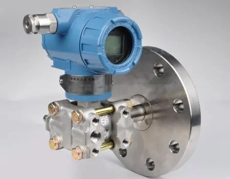
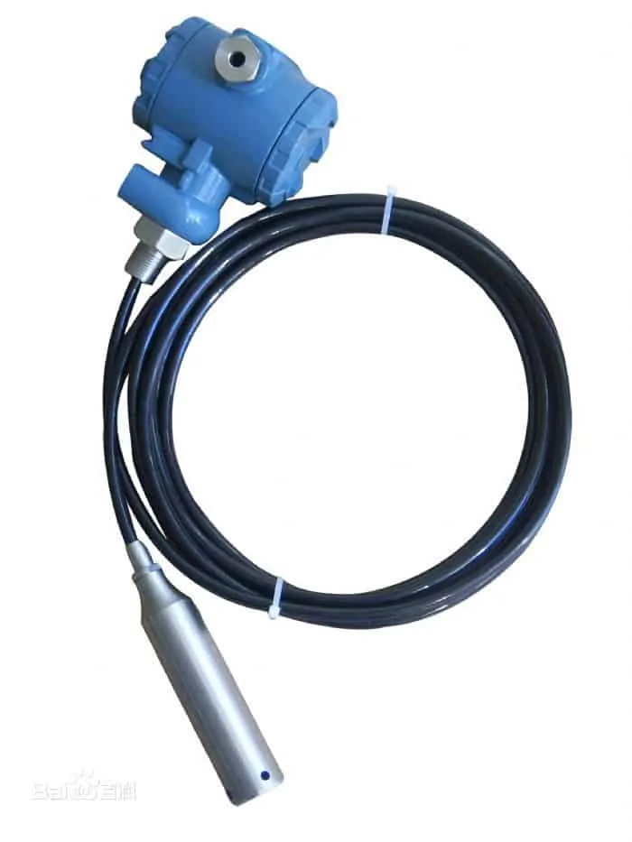
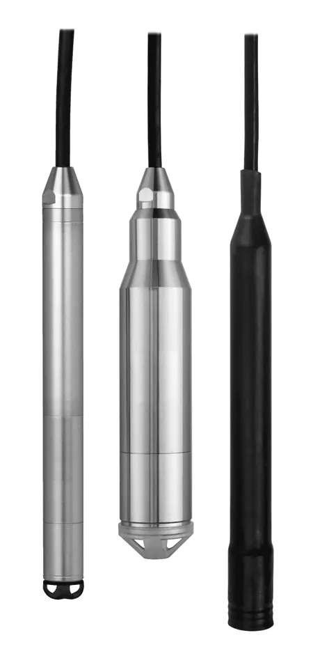
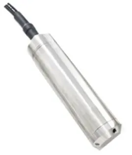
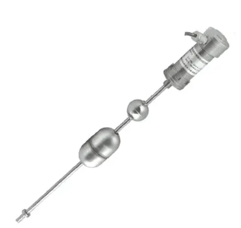
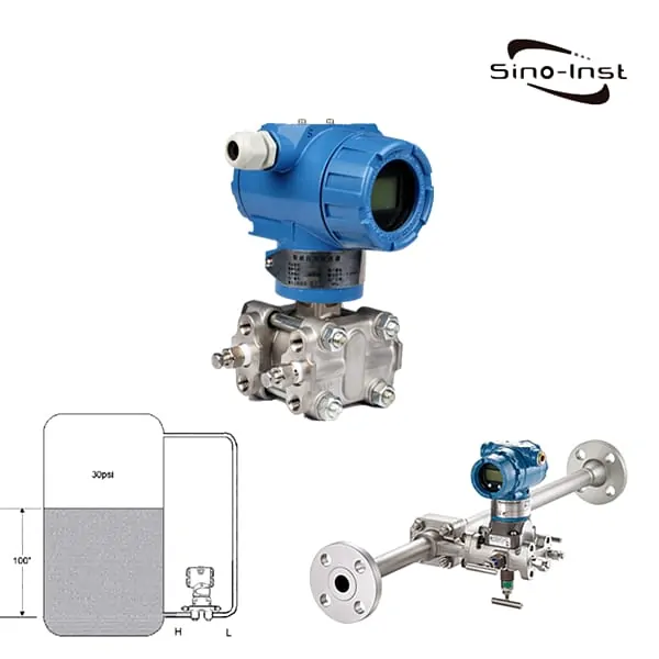
Hydrostatic Pressure Transmitters is an instrument that measures the hydrostatic pressure or differential pressure exerted by a hydrostatic head.
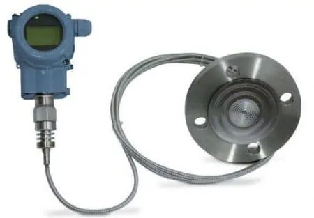
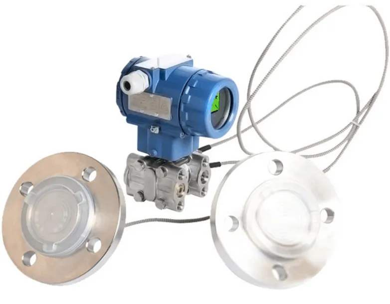
Feel the measured pressure through the remote transmission device installed on the pipeline or container. The pressure is transmitted to the main body of the transmitter through the filling silicone oil (or other liquid) in the capillary tube. Then there is the delta chamber and the amplifier circuit board in the main body of the transmitter. Convert into 4-20mA DC signal output. HP Smart can communicate with a HART handheld communicator. Use it to set, monitor, or form an on-site monitoring system with the host computer.
Hydrostatic Pressure Transmitters are often used to measure the level, flow, and pressure of liquids, gases, or steam under high working pressure environments.
Features of Hydrostatic Pressure Transmitter
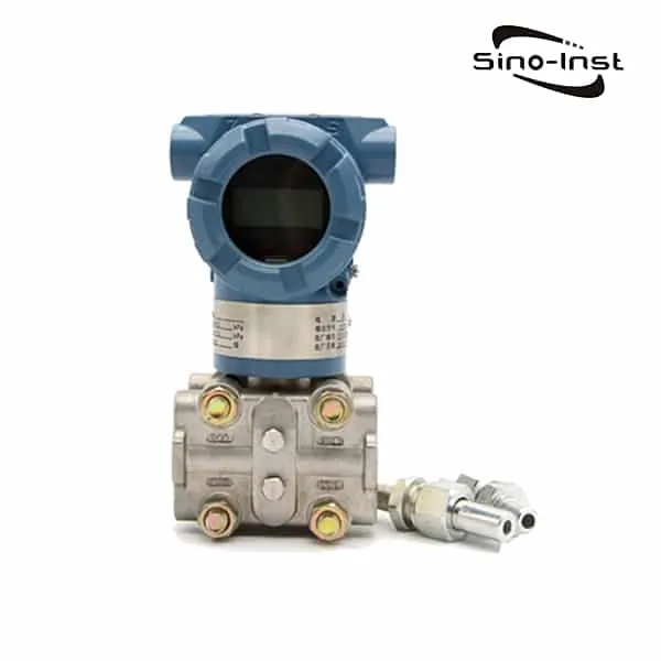
The Hydrostatic pressure transmitter is used to measure the liquid level, flow, and pressure of the liquid, gas or steam under high working pressure, and then convert to 4~20mA DC signal output.
The Hydrostatic pressure transmitter is used to measure the liquid level, flow, and pressure of the liquid, gas or steam under high working pressure, and then convert to 4~20mA DC signal output.
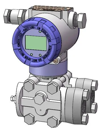
- The high hydrostatic pressure transmitter can measure differential pressure below 32MPa hydrostatic pressure.
- With 32MPa working pressure and overload protection.
- Ensuring reliable application of the transmitter in Hydrostatic pressure systems.
Read more about: Steam pressure transmitter-Pressure measure on steam pipeline
Specifications of Hydrostatic Pressure Transmitter
Measure Range of Hydrostatic pressure sensor:
Differential pressure: 0-1.3-6790KPa
Hydrostatic pressure: 32MPa
- Use object: liquid, gas or steam
- Output signal: 4-20mA dc. Output superimposed HART protocol digital signal (two-wire system)
- Power source: external power supply 24V dc. Power supply range 12V ~ 45V
- Installation in dangerous places:
- Flameproof ExdIIBT5Gb;(explosion-proof certificate no. :CE16.1163)
- Intrinsically safe ExiaIICT4/T5/T6Ga;(explosion-proof certificate no. : CE15.2354X) ;
- Accuracy: ± 0.1%, ±0.2%
- Stability: ±0.25%/6 months of maximum range
| Model | Transmitter type | |||
| HP | Absolute pressure transmitter | |||
| Code | Scale range | |||
| 2 | 0-0.10~3.5kPa(0-10~350mmH2O) | |||
| 3 | 0-0.8~8.0kPa(0-80~800mmH2O) | |||
| 4 | 0-4.0~40kPa(0-400~4000mmH2O) | |||
| 5 | 0-20~200kPa(0-2000~20000mmH2O) | |||
| 6 | 0-70~700kPa(0-0.7~7kgf/cm2) | |||
| 7 | 0-210~2100kPa(0-2.1~21kgf/cm2) | |||
| 8 | 0-700~7000kPa(0-7.0~70kgf/cm2) | |||
| 9 | 0-2.1~21MPa(0-21~210kgf/cm2) | |||
| 0 | 0-4.1~41MPa(0-41~4100kgf/cm2) | |||
| Code | Output form | |||
| E | Linear output 4-20mAdc | |||
| SF | Linear/square root output 4-20mAdc +HART signal,,Full function buttons on site | |||
| F | MODBUS-485 signal | |||
| Code | Structural materials | |||
| Flange connector | Exhaust/Drain valve | Isolation diaphragm | Filling liquid | |
| 22 | 316 Stainless steel | 316 Stainless steel | 316 Stainless steel | Silicone oil |
| 23 | 316 Stainless steel | 316 Stainless steel | Hastelloy C | Silicone oil |
| 24 | 316 Stainless steel | 316 Stainless steel | Monel | Silicone oil |
| 25 | 316 Stainless steel | 316 Stainless steel | Tantalum | Silicone oil |
| 33 | Hastelloy C | Hastelloy C | Hastelloy C | Silicone oil |
| 35 | Hastelloy C | Hastelloy C | Tantalum | Silicone oil |
| 44 | Monel | Monel | Monel | Silicone oil |
| Code | Shell material | Conduit inlet dimensions | ||
| A | Low copper aluminum alloy polyurethane coating | M20×1.5 | ||
| B | Low copper aluminum alloy polyurethane coating | 1/2-14 NPT | ||
| C | Stainless steel | M20×1.5 | ||
| D | Stainless steel | 1/2-14 NPT | ||
| Code | Pressure connection | |||
| L1 | 1/4NPT-18 Internal thread(excluding waist joint standard) | |||
| L2 | 1/2NPT-14 Internal thread | |||
| L3 | M20×1.5 External thread | |||
| Code | Optional parts | |||
| M4 | LCD multi-power digital display head | |||
| B1 | Pipe bending bracket | |||
| B2 | Plate bending bracket | |||
| B3 | Pipe mounting bracket | |||
| C02 | M20×1.5 nut and Φ 14 pressure short tube | |||
| C12 | 1/2NPT-14 external thread and Φ14 pressure short tube | |||
| C22 | 1/4NPT-18 external thread and Φ14 pressure short tube | |||
| C32 | 1/4NPT-18 to M20×1.5 external thread | |||
| C42 | 1/2NPT-14 to M20×1.5 external thread | |||
| C43 | 1/2NPT-14 to 1/4NPT-18 internal thread | |||
| C44 | 1/2NPT-14 to 1/2NPT-14 external thread | |||
| C45 | 1/2NPT-14 to G1/2 external thread | |||
| D1 | The side discharge valve is on the upper part | |||
| D2 | The side discharge valve is on the upper part | |||
| X1 | Oil ban | |||
| Da | Flameproof ExdIIBT5Gb;(explosion-proof certificate no. : CE16.1163) | |||
| Fa | Intrinsically safe ExiaIICT4/T5/T6Ga;(explosion-proof certificate no. : CE15.2354X) |
Hydrostatic Pressure Transmitter Applications
- Viscous medium at high temperature
- Crystallizable medium
- Precipitating medium with solid particles or suspended matter
- Strong corrosive or highly toxic medium
- It can eliminate the phenomenon that the pressure guiding tube leaks and pollutes the surrounding environment. It can avoid the instability of the measurement signal when the isolation fluid is used. The tedious work of frequently supplementing the isolation fluid is required.
- Continuous and accurate measurement of interface and density
- The remote transmission device can avoid the mixing of different instantaneous media. So that the measurement result truly reflects the actual situation of the process change.
- Occasions requiring high hygiene and cleanliness
- For example, in the production of food, beverage and pharmaceutical industries, it is not only required that the parts of the transmitter contacting the medium meet the hygienic standards. It should also be easy to wash. To prevent cross-contamination of different batches of media.
Extended reading: Silicon Pressure Sensor
Hydrostatic Pressure
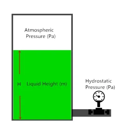
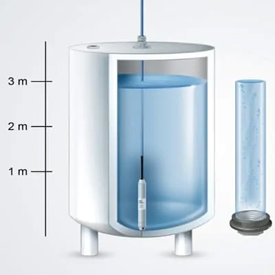
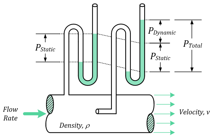
Hydrostatic pressure is the pressure generated by the weight of the liquid above the measurement point when the liquid is stationary. The height of the liquid column with uniform density is proportional to the hydrostatic pressure. As the weight of the fluid exerting downward force from above increases, the hydrostatic pressure increases in proportion to the depth measured from the surface.
Read more about: Differences! Static pressure vs dynamic pressure vs total pressure
If the fluid is inside the container, the depth of the object placed in the fluid can be measured.
The hydrostatic characteristics of a liquid are not constant, and the main factors affecting it are the density and local gravity of the liquid. In order to determine the hydrostatic pressure of a particular liquid, both quantities need to be known.
The deeper an object is placed in a fluid, the greater the pressure it bears. This is because the weight of the fluid is higher than its weight. Due to the weight of the fluid, the denser the fluid above it, the greater the pressure on the submerged object.
Measuring principle
The pressure in the liquid increases as the filling height increases. The hydrostatic pressure is transmitted to the measuring unit through the stainless steel diaphragm. Bubbling, accumulation of liquids, fluctuating electrical characteristics, and container design will not affect the measured value.
Extended reading: What is flush diaphragm?
Formula for calculating hydrostatic pressure
The formula for calculating the hydrostatic pressure of a column of liquid is:
Phyd = h.ρ.g
Prel = h.ρ.g
Pabs = h.ρ.g + Patm
Phyd = Hydrostatic Pressure (Pa)
Prel = Relative Pressure (Pa)
Pabs = Absolute Pressure (Pa)
Patm = Atmospheric Pressure (Pa)
h = Liquid Height (m)
ρ = Liquid Density (kg/m3)
g = Local Gravity (m/s2)
The above calculation formula is also the working principle of hydrostatic liquid level sensor.
Hydrostatic pressure transmitter fault debugging steps:
How to debug the fault of Hydrostatic pressure transmitter
Total Time: 30 minutes
Check if the power supply of the differential pressure transmitter is reversed, and whether the positive, and negative poles of the power supply are connected correctly.
Measure the power supply of the transmitter, whether there is 24V DC voltage. It must ensure that the power supply voltage to the transmitter is ≥12V
(that is, the voltage of the transmitter power input terminal is ≥12V).
If there is no power supply, check whether the circuit is disconnected, whether the instrument is selected incorrectly (input impedance should be ≤250Ω), and so on.
If the pressure transmitter is equipped with a meter head, it is necessary to check whether the dislay meter is damaged. You can short-circuit the two wires of the meter head first. If it is normal after a short circuited, it means the head is damaged.
If the meter head is damaged, Then you need to change the header.
If there is a problem with the differential pressure transmitter, connect the ammeter to the 24V power supply circuit to check if the current is normal.
If it is normal, the transmitter is normal. In this case, check if other instruments in the loop are normal.
Connect the power supply to the transmitter power input terminal, and connect the power cable to the power supply wiring port.
If you still have any question with the selection, application, and use of pressure transmitters, you can just contact our engineer today.
Related Blogs
Extended reading: Use of high temperature melt pressure sensor
Hydrostatic pressure transmitter/sensor measures the level, density, and pressure of liquid, gas, or steam. And then converts it into a 4-20 mA DC signal output. The Hydrostatic pressure transmitter can communicate with the HART communicator intelligently. Use it to set, monitor or form a site monitoring system with the host computer. Use a Hydrostatic pressure sensor to measure tanks, processing vessels, headers, pump inlets and others using hydrostatic pressure to determine the liquid height. SI3051HP Hydrostatic pressure transmitters, with working Hydrostatic pressure up to 32Mpa.
Extended reading: Best Price Ceramic Pressure Sensor
Sino-Inst offers a variety of Hydrostatic Pressure Transmitters for industrial pressure measurement. If you have any questions, please contact our sales engineers.
Request a Quote

Wu Peng, born in 1980, is a highly respected and accomplished male engineer with extensive experience in the field of automation. With over 20 years of industry experience, Wu has made significant contributions to both academia and engineering projects.
Throughout his career, Wu Peng has participated in numerous national and international engineering projects. Some of his most notable projects include the development of an intelligent control system for oil refineries, the design of a cutting-edge distributed control system for petrochemical plants, and the optimization of control algorithms for natural gas pipelines.


