U-Series Liquid Mass Flow Meter

Liquid Mass Flow Meter can perform accurate mass measurements for liquids or slurries. Used for volumetric flow metering of liquids in pipelines. Such as diesel fuel, fuel oil flow measurement.

U-Series Liquid Mass Flow Meter

Liquid mass flow meter, we mean the mass flow meter can measure the flow rate of liquid, like the: diesel fuel, fuel oil, water, caustic, and gases/vapors. And we can use the thermal mass flow meter for the gas flow rates measurement. Coriolis mass flow meter is well known to everyone. Sino-Inst offers liquid mass flow meters based on the Coriolis mass theory.

Sino-Inst offers a variety of mass flow meters for flow measurement. If you have any questions, please contact our sales engineers.

Features of U-Series Liquid Mass Flow Meter

  • High-precision measurement ±0.1~0.2%.
  • Wide application range: 316L stainless steel structure is suitable for a variety of media, and the meter coefficient is not affected by liquid measurement.
  • The gas flow measurement does not require temperature and pressure compensation, and the measurement is convenient and accurate.
  • Multivariable flow: Provide accurate measurement for a series of variables. Including mass flow, volume flow, total flow, density and temperature.
  • Using MVD multivariable digital technology converter: from analog signal processing to digital signal processing. A stable signal can be generated, thereby improving response speed and measurement accuracy.
  • Easy to use: LCD display. Users can directly and conveniently perform configuration operations through touch buttons in English.
  • Reliability and repeatability: The non-wearing movable parts enable the instrument to maintain reliability and repeatability for a long time. And to ensure high-precision flow and density measurement in conventional process control applications.

Specification of U-Series Liquid Mass Flow Meter

Measuring rangeDN6~DN200
Fluid measurement accuracy±0.1~0.2%
Repeatability±0.1~0.25%
Density measurement range0.5~2g/cm3
measurement accuracy±0.002g/cm3
Temperature measurement range-100~+300℃
Precision±1℃
Measuring tube materialSS316L
shell materialSS304
Work pressure0~4.0MPa (high pressure can be customized)
Explosion-proof standardExd(ia)IICT6Gb
Output4-20mA, pulse, RS485
communicationMODBUS, HART
Power220VAC or 24VDC
LCD display contentFlow, temperature, density

Flow Range

ModelDiameter (mm)Recommended flow range (kg/h)Maximum flow range (kg/ h)
CMF-00330-1500-180
CMF-00660-6000-720
CMF-00880-9600-1200
CMF-010100-18000-2100
CMF-015150-36000-4500
CMF-020200-60000-7200
CMF-025250-96000-12000
CMF-032320-180000- 21000
CMF-040400-300000-36000
CMF-050500-480000-60000
CMF-080800-1500000-180000
CMF-1001000-2400000-280000
CMF-1501500-4800000-600000
CMF-2002000-9000000-1200000

Details of U-Series Liquid Mass Flow Meter

details of liquid mass flow meter

U-Series Liquid Mass Flow Meter Applications

The CMF mass flowmeter can be monitored in the following areas to meet the needs of its ingredients, mixing processing and commercial measurement:

  • Chemical industry, such as systems with chemical reactions
  • Petroleum industry, such as moisture content analysis
  • Oil industry, such as vegetable oil, animal oil and other oils
  • Pharmaceutical industry
  • Paint industry
  • Paper industry
  • Textile printing and dyeing industry
  • Fuel industry. Such as oil, heavy oil, coal water slurry and other fuels, lubricants
  • Food industry. Such as dissolved gas drinks, health drinks and other liquids
  • Transportation industry. For example, the metering of pipeline transportation liquid

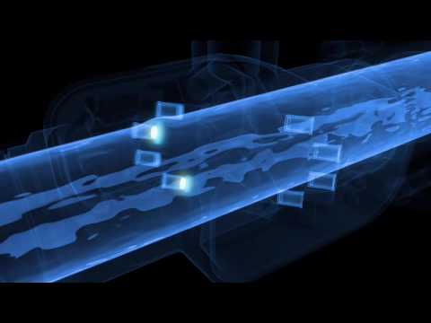
Liquid Mass Flow Meter working principle

Coriolis mass flowmeters measure the force resulting from the acceleration, caused by mass moving toward (or away from) a center of rotation.

This effect can be experienced, when riding a merry-go-round, where moving toward the center will cause a person to have to “lean into” the rotation so as to maintain balance.

As related to flowmeters, the effect can be demonstrated by flowing water in a loop of flexible hose, that is “swung” back and forth in front of the body with both hands. Because the water is flowing toward and away from the hands, opposite forces are generated and cause the hose to twist.

They represent about 21% of all flowmeters sold.

In a Coriolis mass flowmeter, the “swinging” is generated by vibrating the tube(s) in which the fluid flows.

The amount of twist is proportional to the mass flow rate of fluid passing through the tube(s).

Sensors and a Coriolis mass flowmeter transmitter are used to measure the twist and generate a linear flow signal.

How do you calculate mass flow rate?

As shown, when a mass point of mass m moves at a velocity υ in a pipe that rotates at an angular velocity ω for the p-axis, the particle is subjected to acceleration of two components and its force.

a. The normal acceleration is the centripetal force acceleration αr, the magnitude of which is equal to ω2r, the direction is toward the P axis;

b. Tangential acceleration αt is the Coriolis acceleration, the magnitude of which is equal to 2ωυ, and the direction is perpendicular to αr.

Due to the compound motion,

Coriolis Fc=2ωυm acts on the αt direction of the particle, and the pipe acts on the particle with a reverse force of -Fc= -2ωυm.

When a fluid of density ρ flows at a constant velocity in a rotating pipe, any pipe of length Δx will be subjected to a tangential Coriolis force of ΔFc.

Where A is the cross-sectional area of the pipeline. Since the flow rate of the mass flow meter is δm, δm=ρυA.

Therefore, directly or indirectly measuring the Coriolis force generated by the flowing fluid in the rotating pipe can measure the mass flow, which is the basic principle of the Coriolis mass flowmeter.

However, it is difficult to generate Coriolis force by the rotary motion.

At present, the product is replaced by a pipe vibration, that is, a thin-walled measuring tube fixed by two broken ends,at the midpoint of the measuring tube resonance or near resonance frequency.

Excitation, the fluid flowing in the tube generates Coriolis force, causing the opposite direction of deflection in the front and rear half points of the measuring tube. And electromagnetically detecting the amount of deflection to obtain mass flow.

Since the density of the fluid affects the vibration frequency of the measuring tube, and the density has a fixed relationship with the frequency, the mass flow meter can also measure the fluid density.

Read more about: Volumetric Flow Rate To Mass Flow Rate

Tools:

Mass Flow & Density to Volume Flow CalculatorMass Flow Rate Unit ConverterVolume Flow Rate Converter
Volume Flow & Density to Mass Flow CalculatorVolumetric Flow Rate & Pipe Diameter to Flow Speed Calculator

Liquid CO2 Mass Flow Meter

Liquid carbon dioxide refers to the liquefaction of carbon dioxide gas into liquid form under high pressure and low temperature. Liquid carbon dioxide is a refrigerant that can be used to preserve food and can also be used for artificial rainfall. It is also an industrial raw material that can be used to make soda ash, urea and soda.

Generally, a mass flow meter can be used to measure the mass flow of liquid carbon dioxide.
Or, you can also use our spur gear flow transmitter to measure.

Liquid Nitrogen Mass Flow Meter

Coriolis mass flow meters can also measure the mass flow of liquid nitrogen. The measurement effect is also very good.
However, the cost of Coriolis mass flow meters is relatively high.

Therefore, sometimes, we can also use a flow meter for him to measure the flow of liquid nitrogen.

A liquid nitrogen flow meter is a commonly used cryogenic flow meter. The low-temperature turbine flowmeter is a dedicated liquid nitrogen flowmeter. It can also be used to measure cryogenic liquids such as liquid oxygen.

Liquid nitrogen refers to Liquid with extremely low temperatures. In industrial production, liquid nitrogen can be used as a deep refrigerant. The low-temperature turbine flowmeter is used as a liquid nitrogen flowmeter, which can work at a low temperature of -196°C (-320.8 °F). Liquid Nitrogen Flow Meter’s Turbine sensor structure at ultra-low temperature (-196℃) is made of special customized material. Realize the instantaneous and cumulative flow monitoring of liquid nitrogen.

FAQ

The mass flow meter directly measures the mass flow of the medium passing through the flow meter, and can also measure the density of the medium and indirectly measure the temperature of the medium. Since the transmitter is an intelligent instrument with a single-chip microcomputer as the core, more than a dozen parameters can be derived for users to use based on the three basic quantities mentioned above. The mass flow meter has a flexible configuration, powerful functions, and a high performance-price ratio. It is a new generation flow meter.

Classification of mass flow meters:

①Direct mass flow meter
That is, directly detect the amount proportional to the mass flow rate. The detection element directly reflects the mass flow.

②Deduced mass flow meter
That is, a combination of the volumetric flowmeter and density meter is used to measure mass flow. At the same time, the volume flow rate and fluid density are detected. The output signal related to the mass flow rate is obtained through calculation.

③Compensating mass flowmeter
At the same time, the volume flow rate of the fluid and the temperature and pressure of the fluid are detected, and then according to the relationship between the density of the fluid and the temperature and pressure. The density value of the fluid in this state is calculated by the calculation unit. Then calculate the mass flow value of the fluid.

The mass flow meter is a function of fluid volume and fluid temperature and pressure. Is a dependent variable. The quality of a fluid is a quantity that does not change with time, space temperature, and pressure.

The electromagnetic flowmeter is a pure liquid volume measurement instrument.

Flowmeter is one of the important measuring instruments in process automation instruments and devices.

According to the physical properties of the measured medium, it can be divided into liquid flow meters and gas flow meters.

Among them, there are many types of liquid flow meters.

Common liquid flow meters are:

More digital liquid flow meters

You may like:

Sino-Inst offer over 10 liquid flow meters, with Best Price.

A wide variety of industrial flow meters options are available to you, such as free samples, paid samples. All of our flow meters can wokrk with the AMS NEW TREX. About 13% of these are magnetic flow meter. 14% are Insertion Magnetic Flow Meter. 25% are Venturi flow meter. 13% are Handheld ultrasonic flow meter, and others are Liquid Turbine Flow Meters.

Sino-Inst is mass flow meter suppliers, located in China. Mass flow meter products are most popular in North America, Mid East, and Eastern Europe.

The United States, and India, which export 99%, 1%, and 1% of ultrasonic level transmitter respectively.

You can ensure product safety by selecting from a certified supplier, with ISO9001, ISO14001 certification.

Request a Quote

Ultrasonic flow measurement


Ultrasonic Flow Measurement, Industrial Inline Flow Measurement.

Ultrasonic flow meters, using the ultrasonic principle, measure the velocity of flow.

We can use a different type of ultrasonic flow meters, like: Portable ultrasonic flow meter, Handheld ultrasonic flow meter, Clamp-on Ultrasonic Gas Flow Meter.

For airflow, natural gas, water, velocity measurement. There are two types of ultrasonic flow meter technologies: Doppler shift and transit-time. Transit-time measures the time differential between signals sent upstream and downstream.

The differential is directly proportional to the velocity of the water.

Transit-time meters are best used for measuring the flow of clean liquids and, as a result, are the most popular type of ultrasonic meter. 

Doppler shift measures the difference in frequency of the sound wave, reflected off gas bubbles or particles in the flow stream, and is suitable for aerated or dirty liquids.

Products for Ultrasonic Flow Meters solutions

Specifications of Ultrasonic Flowmeters

Item

Principle and parameters

Converter

Principle

Transit-time,4 byte floating-point operation in accordance with IEEE754

Accuracy

Inline type:flow meter:±0.5%; heat meter:±1.0%

Clamp on type:flow meter:±1.0%; heat meter:±2.0%

Insertion type:flow meter:±1.0%; heat meter:±2.0%


Operation

4-key manipulation with magnetic bar touch or figer touch;

simulation keyboard software

Output

One way 4-20mA analog output

One way OCT pulse signal output

One way Relay output

Input

3 way 4-20mA analog input,accuracy:0.1%;

Acquisition signal of temperature,press and liquid level

Achieve heat measurement by connecting 3-wired PT100

Temperature sensor

Data interface

RS485 serial interface,upgraded by computer,support MODBUS communication protocol

Special cable

Twisted-pair shielded cable and cable length should be no more than 50 m.Transmission distance can achieve 1 km if select the RS 485 interface

pipeline

Pipe material

Steel,stainless,copper,cement,PVC,aluminum,glass steel, cast iron

Pipe diameter

DN15mm-DN6000mm

Straight pipeline

Transducers installation points should be:10 diameters’ straight pipeline from upstream transducer ,5 diameters’ 

straight pipeline from the downstream transducer ;30 diameters’ straight pipeline from the pump

Measuring

Medium


Liquid type

Single liquid that can conduct sound wave,such as water,

Seawater, sewage,plant effluent,chemicals,alcohol,beer,oil

etc.

Fluid temperature

-30℃-160

Turbidity

10000ppm,with little bubble

Fluid velocity

0m/s-7m/s

Working

Environment

Temperature

Converter:-20℃-60℃;transducer:-30-160

Humidity

Both of the converter and transducers can work under water,depth underwater ≤2m(After completely sealing)

Power supply

DC8-36V;AC85-264V(optional)

Power consumption

1.5W

ultrasonic flow meter pDF

The Working Principle of Ultrasonic Flow Measurement

Video source: https://www.youtube.com/embed/Bx2RnrfLkQg?start=16

Ultrasonic flowmeters use sound waves to determine the velocity of a fluid flowing in a pipe.

At no flow conditions, the frequencies of an ultrasonic wave transmitted into a pipe, and its reflections from the fluid are the same.

Under flowing conditions, the frequency of the reflected wave is different, due to the Doppler effect.

When the fluid moves faster, the frequency shift increases linearly.

The transmitter processes signals from the transmitted wave, and its reflections to determine the flow rate.

You may like: Digital Flow Meters Guide| Liquid and Gas

Ultrasonic flow meter advantages and disadvantages

Generally, an ultrasonic flow meter is the device, that uses ultrasound to measure the velocity of liquid flow, that helps in determining the volume of liquid flow also.

The ultrasonic flow meters are made using the ultrasonic transducers, which are clamped to the external surface of a pipe, to generate the ultrasonic pulses through the pipe.

When the liquid flows inside the pipe, it creates the time difference in the pulses, and these are examined to calculate the accurate flow velocity of the liquid.

There are many advantages of using the ULTRASONIC flow meters which include:

  • The electronics in the ultrasonic flow meter includes ultrasonic flowmeter detector which compensates and adapts to the changes in the profile of the flow, type of the liquid and material of the pipe.
  • A portable ultrasonic flow meter converter can be used as a direct method to determine the flow rates effectively when compared to the other flow systems.
  • Ultrasonic flow meter converter is inexpensive to use and maintain when compared to the other mechanical flow meters as they are no moving parts in these flow meters.
  • Their design is highly sophisticated and they do not obstruct the liquid flow, so they can be used for sanitary, corrosive and abrasive liquids.

These are the advantages of the ultrasonic flow meters and there are many disadvantages of the Ultrasonic flow meter which include:

  • The main disadvantage of the ultrasonic flow meter is the cost. The cost of the flow meter is very high when compared to the other types of mechanical flow meters.
  • The ultrasonic flow meters are sophisticated when compared to the mechanical flow meters, so it needs experts to repair and maintain the flow meters.

These are the advantages and disadvantages of the ultrasonic flow meters.

Ultrasonic flow meter Types

  1. According to the measurement principle

(1) Time difference method ultrasonic flowmeter;
(2) Frequency difference method ultrasonic flowmeter;
(3) Phase difference method ultrasonic flowmeter;
(4) Doppler ultrasonic flowmeter;
(5) Ultrasonic flowmeters for partially full pipes and river channels that combine liquid level measurement and average velocity measurement.

  1. According to usage

(1) Portable ultrasonic flowmeter;
(2) Fixed (standard pipe section) ultrasonic flowmeter.

  1. According to the installation method of the transducer

(1) Standard pipe section ultrasonic flowmeter;
(2) Clip-on ultrasonic flowmeter;
(3) On-site plug-in ultrasonic flowmeter with hole opening.

  1. According to whether the transducer is in contact with the fluid

(1) Immersion (contact) ultrasonic flowmeter;
(2) Non-invasive (non-contact) ultrasonic flowmeter.

  1. According to the nature of the measured fluid

(1) Liquid ultrasonic flowmeter;
(2) Gas ultrasonic flowmeter.

  1. According to the number of transducer channels

(1) Mono ultrasonic flowmeter;
(2) Two-channel ultrasonic flowmeter;
(3) Multi-channel ultrasonic flowmeter.

Extended Reading: Inline Ultrasonic Flow Meter

Ultrasonic Clamp on Flow Meter is composed of an integrated host and external clamp on sensors. Clamp on Flow Sensors are available at room temperature and high temperature.

Clamp on flow meter (Model: 2000) is composed of an integrated host and ultrasonic clamp on sensor. Clamp on flow meter is widely used in online flow measurement of various liquids. Just stick the external clamp sensor on the pipe surface. Compared with the traditional flowmeter, it does not need to cut off the pipe and flow. The installation is convenient and quick, and the non-destructive installation is truly realized.

Extended reading: Ultrasonic flow detectors types

Portable Ultrasonic Flow Meter is a handheld ultrasonic flow meter. The clamp-on sensor is used to measure liquid flow in industrial pipelines.

Handheld ultrasonic flow meter realizes the non-contact measurement of liquid flow. Also often referred to as Portable Clamp-On Ultrasonic Flow Meter for Liquids.

Handheld Ultrasonic Flow Meter ( Model:2000H) has been successfully applied to measurement work in various industries. The measuring range is 20-6000mm (0.5-20 inches). A non-contact measurement method is adopted. Flexible operation and easy to carry. Conductive or non-conductive, corrosive or non-corrosive liquids can be measured. Various fluids: water, pure water, sewage, sea water, chemical fluids, river water, fuel Oil etc. can be measured.

Extended reading: Portable ultrasonic flow meter for water

Ultrasonic flow meter price

Sino-Inst offers Ultrasonic flow meters with the best quality and best price.

The reference price is between USD 150-700.

The price of ultrasonic flow meter is affected by:

  • Types of sensors
  • Materials
  • Cable length

All of our Flow Meters can work with the NEW AMS TREX !

Ultrasonic flow meter manufacturer

Sino-Inst offers 20 Ultrasonic flow meter products, with Best Price.

Sino-Inst is the manufacturer and supplier of ultrasonic flow meters.

About 13% of these are Petroleum& Chemical flow meters, 4% are water treatment flow indicators. The best Reference price is USD 2000-7000.

A wide variety of ultrasonic flow meter options are available to you, such as free samples, paid samples.

Sino-Inst is clamp-on ultrasonic flow meter suppliers, located in China.

Clamp-on ultrasonic flow meter products are most popular in North America, Mid East, and Eastern Europe.

The United States, and India, which export 99%, 1%, and 1% of ultrasonic level transmitter respectively.

You can ensure product safety by selecting from a certified supplier,

with ISO9001, ISO14001 certification.

In addition to measuring flow rate, ultrasonic technology can also be used to measure liquid level.
The ultrasonic liquid level sensor is also an excellent product for measuring the liquid level of the tank.

Procurement Guide: Ultrasonic liquid level sensors

CO2 Cylinder | Portable Liquid Level Gauge

Frequently
Asked
Questions

Fuel flow meters, also known as turbine flow meters, are the main types of speed flow meters. A freely rotatable impeller is installed in the fluid flowing pipe. When the fluid passes, its motion can make the impeller rotate. The larger the fluid flow rate, the larger the kinetic energy and the higher the impeller speed.

The fluid flow can be determined by measuring the number of revolutions or the number of revolutions of the impeller.

Ultrasonic flow detector is also an ultrasonic sensor. Or called an ultrasonic flowmeter.
Ultrasonic flow detector is composed of sensor and host. The host has wall-mounted, handheld, portable, etc. Sensors are classified into the following models according to the measuring pipe diameter and measuring temperature. It can help users measure pipeline flow under various working conditions.

Optional Transducer

Ultrasonic flowmeter refers to a flowmeter developed based on the principle that the propagation velocity of ultrasonic waves in a flowing medium is equal to the vector sum of the average velocity of the measured medium and the velocity of sound waves in a stationary medium.

It is mainly composed of transducer and converter, and there are different types such as Doppler method, velocity difference method, beam shifting method, noise method and correlation method.

Clamp-on or tube-segment ultrasonic flow meter is based on the principle of “velocity difference method”. It is an instrument for measuring the liquid flow in a circular tube.

Ultrasonic flow meters for measuring liquid flow. Measurement linearity is better than 0.5%. Repeatability accuracy is better than 0.2%. The time difference measurement resolution of up to 40 picoseconds enables the measurement accuracy to reach ±1%.

When choosing an ultrasonic flowmeter, the following points are mainly considered:

1.Measuring medium. 2. Pipe material. 3. Velocity range. 4. Diameter range. 5. Applicable temperature. 6. Medium turbidity. 7. Pipe lining. 8. Acceptable form of installation.

Related Blogs

Sino-Inst, Manufacturer for Ultrasonic Flow Meters. It can measure a single sound-conducting liquid medium of DN 25—150mm. It can measure even liquids such as water, sea water, oil, and slurry.

Sino-Inst’s Ultrasonic Flow Meter, made in China, Having good Quality, With better price. Our flow measurement instruments are widely used in China, India, Pakistan, US, and other countries.

Clamp-on Ultrasonic Gas Flow Meter

Clamp-on Ultrasonic gas flow meters, also called ultrasonic natural gas flow meters, measure liquids, and gas in industrial flow measurement applications.

Ultrasonic gas flow meters are one of the most reliable solutions,

for challenging gas flow measurement applications. (Kind like the portable ultrasonic)

Because the sensor is clamped on to the outside of the pipe,

it is immune to the process compatibility,

concerns of an in-line flow metering technology (What is a flow meter? ).

​​It is now possible to measure natural gassteamcompressed airhydrogen

compressed air and many more using clamp-on flow meters.

Our transducer technology is also ideal for shale gas,

and coal seam gas wellhead applications.

SI-3128 wall mounted ultrasonic flow meter could be applied to a variety of liquid applications,

including ultra-pure liquids, water, chemicals, raw sewage,

reclaimed water, cooling water, river water, plant effluent, alcohol, beer, etc.

What are the types of flow meter?

Features of Clamp-on Ultrasonic Gas Flow Meter

Ultrasonic Flow Meter SI-3128
  • Accuracy: 1%
  • Ingress protection level: IP67 (transmitter), IP68 (sensor)
  • Wide measurement range, pipe size from DN15mm to DN6000mm.
  • Three installation types: wall mounting, DIN-rail mounting, explosion-proof box mounting
  • Could operate with temperature sensors for heat/energy measurement.
  • Could be installed without shut down equipment operation

Specifications for Clamp-on Ultrasonic Gas Flow Meter

Items

Performance Parameter


      Host


Principle

Transit- time ultrasonic flowmeter

Accuracy

±1%

Display

2X20 character LCD with backlight, support the language of Chinese, English and Italy

Signal

Output

1 way 4~20mA output, electric resistance 0~ 1K, accuracy 0. 1%(optional)

1 way OCT pulse output(Pulse width 6~1000ms, default is 200ms)

1 way Relay output


Signal

Input

3 way 4~20mA input, accuracy 0. 1%, acquisition signal such as temperature, press and liquid level

Connect the temperature transducer Pt100, can finish the heat/energy measurement

Data

Interface

Insulate Rs485 serial interface, upgrade the flowmeter software by computer, support the MODBUS

Special Cable

Twisted-pair cable, generally, the length under 50 meters ; Select the RS485, transmission distance can over 1000m

Pipe

Installation

Condition

Pipe

Material

Steel, Stainless steel, Cast iron, Copper, Cement pipe, PVC, Aluminum, Glass steel product, liner is allowed

Pipe

Diameter

DN32~6000mm

Straight

Pipe

Transducer installation should be satisfied: upstream10D, downstream 5D, 30D from the pump

Measuring

Medium

Medium

water,sea water ,alcohol,Acid and alkali,waste water,beer,all kinds of oil Single liquid can transmit sound wave.

Temperature

-30~160℃

Turbidity

No more than 10000ppm and less bubble

Flowrate

0~±7m/s,Forward and backward measurement

Work environment

Protection grade

Host:IP67;flow sensor:IP68

temperature

Host:-20~60℃;flow sensor:-30~ 160℃

Humidity

Host: 85%RH; Flow sensor:can measure under water, water depth^2m (tansducer sealed glue)

Power Supply

DC8~36V or AC85~264V

Power

Consumption

1.5W

Dimension

132*150*85mm(host)

You may like: Vortex shedding flow meter

Gases that can be measured with ultrasonic clamp-on flowmeters include:

Compressed AirHydrogenOxygen
NitrogenSteamNatural Gas
PropaneButaneCorrosive Gases
Erosive GasesHigh Purity GasesSterile Gases
Toxic GasesInert GasesCompressed Air

What is ultrasonic gas meter?

Ultrasonic flowmeters use sound waves to determine the velocity of a fluid flowing in a pipe.

At no flow conditions,

the frequencies of an ultrasonic wave transmitted into a pipe,

and its reflections from the fluid are the same.

Under flowing conditions, the frequency of the reflected wave is different due to the Doppler effect.

When the fluid moves faster, the frequency shift increases linearly.

The transmitter processes signals from the transmitted wave,

and its reflections to determine the flow rate.

Transit time ultrasonic flowmeters send and receive ultrasonic waves,

between transducers in both the upstream and downstream directions in the pipe.

At no flow conditions,

it takes the same time to travel upstream and downstream between the transducers.

Under flowing conditions, the upstream wave will travel slower and take more time than the (faster) downstream wave.

When the fluid moves faster, the difference between the upstream and downstream times increases.

The transmitter processes upstream and downstream times to determine the flow rate.

They represent about 12% of all flowmeters sold.

The ultrasonic principle can also be used to measure water depth. Please refer to Portable Ultrasonic Water Depth Gauge for water depth measurement.

You may like: Nitrogen flow meter

How does a clamp-on flow meter work?

A clamp-on ultrasonic gas flow meter produces signals,

that is five to ten times more powerful,

then those of traditional ultrasonic transducers.

The new clamp-on transducers produce clean, coded signals with very minimal background noise.

The result is that a clamp-on gas flow meter can now provide optimum performance,

even with low-density gas applications.

Today, our ultrasonic clamp-on gas flowmeters such as the SI-3128 can measure the flow of any gas,

and then calculate mass flow using a pressure transmitter connected to the analog input.

Inline ultrasonic flowmeters

The SI-3000H Portable Ultrasonic Flowmeter is a widely used time difference ultrasonic flowmeter,

for on-line calibration and inspection of liquid flow in various industrial sites.

Handheld ultrasonic flow meter, also known as Portable Doppler flow meter, or Inline ultrasonic flow meter.

SI-2000H handheld ultrasonic flow meter is a representative of portable ultrasonic flow meters.

More Gas Flow Meters

Sino-Instrument offers 20 Gas flow meter products, with Best Price.

About 13% of these are Petroleum& Chemical flow meters, 4% are water treatment flow indicators.

The best Reference price is USD 2000-7000.

A wide variety of gas flow meter options are available to you, such as free samples, paid samples.

Sino-Instrument is clamp-on ultrasonic flow meter suppliers, located in China.

clamp-on ultrasonic flow meter products are most popular in North America, Mid East, and Eastern Europe.

The United States, and India, which export 99%, 1%, and 1% of ultrasonic level transmitter respectively.

You can ensure product safety by selecting from a certified supplier,

with ISO9001, ISO14001 certification.

Of course, you can also choose other gas flow measurement instruments, like:

https://www.drurylandetheatre.com/coriolis-mass-flow-meter-si3131/
https://www.drurylandetheatre.com/steam-flow-meter-inline-vortex-flow-meters/
https://www.drurylandetheatre.com/magnetic-flow-meters/
https://www.drurylandetheatre.com/si-rsl-thermal-mass-flowmeters/

Request a Quote

Turbine Flow Meters

Turbine Flow Meters for Liquid

Turbine flow meters are flow sensors work for the inline liquids.

Turbine flow meters are cost-effective and offer reliable,

measurement with minimal flow meter maintenance required.

Turbine flow meters measure the velocity of liquids, gases, and vapors in pipes,

such as hydrocarbons, chemicals, water, cryogenic liquids, air, and industrial gases.

Types of flow meter

Featured Turbine Flow Meters

Gas Turbine Flow Meters

Liquid Turbine Flow Meters

Insertion Turbine Flow Meters

https://www.drurylandetheatre.com/insertion-turbine-flow-meter/

Sanitary flow meter

Turbine Flow Meter Working Principle

Turbine meters are simple to operate and maintain,

and in-service worldwide as a reliable, cost-effective method,

for achieving accurate flow measurement.

Turbine flow meters are designed to maximize throughput,

and minimize pressure drop, maintain high flow rates over an extended flow range,

and offer pulse output that is linear to the flow rate.

The turbine meters also minimize fiscal measurement uncertainty,

by delivering high-frequency pulse resolution,

to account for minute increments of the flow rate.

Turbine flow meters use the mechanical energy of the fluid to rotate a “pinwheel” (rotor) in the flow stream.

Blades on the rotor are angled to transform energy,

from the flow stream into rotational energy.

The rotor shaft spins on bearings.

When the fluid moves faster, the rotor spins proportionally faster.

Turbine flow meters now constitute 7% of the world market.

Shaft rotation can be sensed mechanically or by detecting the movement of the blades.

Blade movement is often detected magnetically,

with each blade or embedded piece of metal generating a pulse.

Turbine flowmeter sensors are typically located external to the flowing stream,

to avoid material of construction constraints that would result,

if wetted sensors were used.

When the fluid moves faster, more pulses are generated.

The transmitter processes the pulse signal to determine the flow of the fluid.

Transmitters and sensing systems are available to sense flow,

in both the forward and reverse flow directions.

You may like: Industrial flow meters

Turbine flow meter equation


The relationship between volumetric flow rate of the turbine flowmeter and the frequency of the pulses generated by the pickup sensor can be expressed in the form of the equation:

f = kQ

Where,
f = Frequency of pulses generated by pickup sensor(Hz, equivalent to pulses per second)
Q = Volumetric flow rate (e.g. litres/min)
k = “K” factor of the turbine meter (e.g. pulses per litre)

Turbine Meter K-Factor
The turbine meter measures volumetric flow, however the pulses produced vary depending on the meter. The variation is accounted for by a K-factor. The K-factor is the number of pulses per unit volume. It is primarily determined by the size and type of the turbine meter. Due to manufacturing tolerances, the actual K-factor can vary between similar models. The K-factor is applicable only to the fluid for which the meter was calibrated in the factory.

You may like Coriolis mass flow meter 

Turbine flow meter advantages and disadvantages

Advantages of Turbine Flow Meters

  1. High precision, generally up to ± 1% R, ± 0.5% R.
  2. Output pulse frequency signal, suitable for total metering and connection with a computer, no zero drift, strong anti-interference ability.
  3. Compact and lightweight, easy installation and maintenance, and large-circulation capacity.
  4. Good repeatability, short-term repeatability of 0.05 ~ 0.2%, due to good repeatability, frequent calibration or online calibration can get very high precision.
  5. A special type of sensor can be designed according to user needs, such as low-temperature type, two-way, downhole type, mixed sand special type.
  6. Pressure compensation can be performed under the pressure state in which the gas to be measured is stable.
  7. The turndown is wide, medium and large caliber up to 1:20, small-caliber is 1:10.

Disadvantages of Turbine Flow Meters

  1. Need to be calibrated regularly, there is no way to maintain accuracy for a long time, can not work continuously for a long time.
  2. The cleaning requirements of the medium are high, but the filter can be installed.
  3. The flowmeter has a large influence on the flow velocity distribution (flow regulator can be installed).
  4. It is not suitable for places where the flow rate is drastically changing.
  5. Not suitable for testing of corrosive media.

You may like:Wastewater Flow Meter

Application Industries

  • Oil & Gas
    • Water injection
    • Test and production separators
    • Disposal wells
    • Hydraulic fracturing
    • Chemical injection
    • Natural gas pipelines
  • Aerospace/Defense
    • Engine Testing
    • Fuel flow measurement
    • Shipboard reverse osmosis systems
    • Monitor fuel supply to ship engines
  • Pharma-Bio Tech, Food & Beverage
    • Sanitary measurement
    • Pill coating
  • Power Generation
    • Custody transfer
  • Industrial & Municipal
    • Building automation
    • HVAC
    • Water metering
  • Cryogenics
    • Liquids measurement for plant applications and truck deliveries

Turbine Flow Meters Price

Sino-Instrument offers all kinds of Turbine flow meters, made in China. Best Quality, and Best Price!

The price of Turbine Flow Meter is around USD400-700/pc,

which will be affected by:

  • Fluid Type
  • Viscosity
  • Connection
  • Pipe Sizing
  • Process Temperature (min & max)
  • Flow Range (min & max)
  • Pressure Range (min & max)
  • Accuracy Range
  • Specific Application

All Flow Meters can work with the NEW AMS TREX, HERE!

Sino-Instrument, Manufacturer for turbine flow meters,

like: gas turbine flow meter,

liquid turbine flow meter, sanitary turbine flow meter,

insertion turbine flow meter, steam turbine flow meter,

and natural gas turbine flow meter.

Sino-Instrument’s turbine flow meters, made in China,

Having good Quality, With better price.

Our flow measurement instruments are widely used in China, India, Pakistan, US, and other countries.

Request a Quote

Coriolis Flow Meter

Coriolis flow meter is also called Coriolis mass flow meter. Based on the principles of Micro motion mechanics. Coriolis meters provide extremely accurate mass or volume flow, density and temperature measurement.

A Coriolis flow meter is a type of mass flow meter. It is designed differently and works differently than thermal or differential mass flow meters. Coriolis meters provide extremely accurate mass or volume flow, density and temperature measurement with few moving parts and no straight pipe requirements.

Sino-Inst offers a variety of  Mass Flow Meters for flow measurement. If you have any questions, please contact our sales engineers.

Guess You’ll Like:

Coriolis flow meter diagram

How does a Coriolis flow meter work?

Where is Coriolis flow meter used?

Coriolis flow meter installation

Coriolis flow meter price

Features of Coriolis Flow Meter

  • Directly measure the mass flow of fluid in the pipeline
    • The measurement accuracy is high and the repeatability is good. It can directly measure the fluid mass flow in a large range
  • High measurement accuracy
    • The mass flow measurement accuracy of this flowmeter is 0.2 level
  • Stable and reliable work
    • There are no obstacles and moving parts in the fluid measuring tube, so it has high reliability and long life.
  • Adapted fluid medium surface width
    • In addition to uniform fluids with general viscosity, it can also measure high-viscosity fluids (honey, oil slurry, etc.).
    • It can measure not only the fluid parameters of a single solution, but also multiphase flow.
    • Whether the medium is laminar or turbulent, it does not affect its measurement accuracy.
  • Wide application environment
    • It is suitable for petrochemical, chemical, metallurgical, pharmaceutical, paper, food, energy and environmental protection industries.
    • In the process of inspection and control and custody transfer measurement and other occasions.
    • Has been widely used,
  • Multiple real-time online measurement and control functions
    • In addition to mass flow, the density and temperature of the fluid can also be directly measured.
    • The intelligent flow transmitter can provide a variety of parameter display and control functions. It is a multi-function flow measurement and control instrument.
  • Good scalability
    • The company can design and manufacture mass flow meters with special specifications and special functions according to user needs.
    • It can also perform remote monitoring operations.

Specifications of Coriolis Flow Meter

Measured mediumLiquid, gas
Measuring diameter1mm~300mm
Measurement itemsMass flow, density, temperature, volume flow, concentration
Density measurement range0.2g/cm3~2.5g/cm3
Medium temperature-200℃~+300℃
Flow measurement errorLiquid 0.2%R+Cz, 0.15%R+Cz, gas 0.5%R+Cz, 1.0%R+Cz,
Density measurement error0.002g/cm3
Temperature measurement error≤1℃
Signal form4~20mA, O~2kHZ, RS485, Hart
Power supply24VDC
Measuring tube material304, 316, can also be negotiated and provided according to user requirements
Explosion-proof gradeExd(ib)IICT2~T5, ExdIICT4
Enclosure ratingIP67
Flange standardNational standard GB/T series standards can also be processed according to user requirements.
Instrument output forma. Current output: 4-20mA; power supply: 13-28VDC, three-wire system;
b. Pulse output: 0~2KHZ; power supply: 13-28VDC; optocoupler output>3mA;
c, RS485 interface
d, HART communication;
Instrument wiringa. The electrical connection port specification of the flowmeter signal output line is: M20 × 1.5; it can also be customized according to user requirements.
b. The 4-20mA current output is a three-wire system;
c. The pulse output is a three-wire system. 

Read more about: The Pros and Cons of Micro Motion Flow Transmitters

Structure of Coriolis Flow Meter

Coriolis mass flowmeter consists of two parts: flow sensor and converter (or flow computer).

The following figure shows an example of a flow sensor, which mainly consists of a measuring tube 2 and its supporting tube 1, a driving coil 4 in the measuring tube vibration excitation system, an electromagnetic detection probe 3 and 6 for detecting the deflection of the measuring tube, and a correction measuring tube material Yang Yang The temperature measurement components and other components affected by the modulus temperature.

U-tube sensor structure diagram
1 Support tube
2 Measuring tube
3 and 6 Magnetic detection probe
4 Drive coil
5 shell

The converter is mainly composed of the vibration signal generation unit, signal detection and signal processing unit of the vibration excitation system; the flow computer also has the functions of configuration setting, engineering unit conversion, signal display and communication with the host computer.

Extended reading: U-series Liquid Mass Flow Meter | Liquid-slurry flow measure

How Does a Coriolis Flow Meter Work?

As shown in the figure, when a mass point with a mass of m moves at a speed υ in a pipe rotating at an angular velocity ω on the p axis, the mass point is subjected to the acceleration and force of two components.

a. Normal acceleration is the centripetal force acceleration αr, its magnitude is equal to ω2r, and the direction is toward the P axis;
b. Tangential acceleration αt is Coriolis acceleration, its magnitude is equal to 2ωυ, and the direction is perpendicular to αr.
Due to the compound motion, Coriolis Fc=2ωυm acts in the αt direction of the particle, and the pipe acts on the particle with a reverse force -Fc= -2ωυm.

When a fluid with a density of ρ flows at a constant speed υ in a rotating pipe, any pipe with a length of Δx will experience a tangential Coriolis force of ΔFc.

(1)

In the formula, A-the internal cross-sectional area of the pipeline. Since the mass flow rate is δm, δm=ρυA.
And so

(2)

Therefore, the mass flow can be measured by directly or indirectly measuring the Coriolis force generated by the fluid flowing in the rotating pipe. This is the basic principle of the Coriolis mass flowmeter.

However, it is difficult to generate Coriolis force by rotating motion. The current products are all replaced by pipe vibration, which is a thin-walled measuring tube fixed by two broken ends. At the midpoint, it is excited at or near the resonance of the measuring tube. The fluid flowing in the tube generates Coriolis force, which causes the two halves of the measuring tube to be deflected in opposite directions. Electromagnetic method is used to detect the amount of deflection to obtain the mass flow rate.

The fluid density will affect the vibration frequency of the measuring tube. The density has a fixed relationship with frequency. Therefore, mass flow meters can also measure fluid density.

OMEGA Engineering has a great explanation video about Coriolis Flow Measuring Principle. Let’s take a look together.

Video source: https://www.youtube.com/watch?v=2vjQ1GwAviM&feature=emb_logo

Applications of Coriolis mass flow meter

Coriolis Flow Meter can play a very effective role in the batching and batch measurement of various feeds in the following fields. The measurement and control of material flow in the process. The rapid and changeable density measurement. As well as product quality monitoring and other aspects.

Coriolis Flow Meter is mainly used to measure the mass flow and total volume and density of the medium. At the same time, it can also measure the volume flow and total volume, the temperature of the medium, the water content, the alcohol content of alcohol, and the concentration of two liquids that are more uniformly mixed. , The ratio of raw materials in the process flow, etc.

Applications of Coriolis mass flow meter

It is mainly applicable to the following industries:
(1) Petroleum industry, such as crude oil production measurement, water cut, single well production measurement, crude oil transportation measurement
(2) Chemical industry
(3) Food industry
(4) Pharmaceutical manufacturing industry, such as liquid medicine production and measurement
(5) Papermaking industry, such as pulp metering
(6) Textile printing and dyeing industry
(7) Energy transmission measurement, such as liquefied gas measurement
(8) Environmental protection industry, such as sewage treatment; measuring slurry density during desulfurization

Extended reading: Featured Hydraulic Flow Meters For Sale

Advantages and Disadvantages of coriolis flow meter

Advantage

  • The Coriolis mass flow meter directly measures the mass flow rate with high measurement accuracy.
  • It can measure a wide range of fluids, including high-viscosity liquids, slurries containing solids, liquids containing trace gases, and medium and high-pressure gases with sufficient density.
  • The measuring tube has a small vibration amplitude and can be regarded as a non-moving part, and there are no obstructions and moving parts in the measuring pipe.
  • It is not sensitive to the flow velocity distribution of the upflow, so there is no requirement for upstream and downstream straight pipes.
  • The measured value is not sensitive to the fluid viscosity, and the change of fluid density has little effect on the measured value.
  • Multi-parameter measurement can be done, such as measuring density at the same time, and deriving the concentration of solute in the measurement solution from this.

Disadvantage

  • The instability of the zero point of the Coriolis mass flowmeter results in zero drift, which affects the further improvement of its accuracy. Many types of meters have to divide the total error into two parts, the basic error and the zero point instability measurement.
  • Coriolis mass flow meters cannot be used to measure low-density media and low-pressure gases; the gas content in the liquid exceeds a certain limit (varies by model), which will significantly affect the measured value.
  • Coriolis mass flowmeters are more sensitive to external vibration interference. In order to prevent the impact of pipeline vibration, most models of Coriolis mass flowmeters require relatively high installation and fixation of flow sensors.
  • It cannot be used for larger pipe diameters, and is currently limited to 150 (200) mm or less.
  • The inner wall of the measuring tube is worn, corroded, or deposited and scaled, which will affect the measurement accuracy, especially for the Coriolis mass flowmeter of the thin-walled tube.
  • The pressure loss is relatively large, which is equivalent to that of volumetric meters. Some Coriolis mass flow meters are even 100% larger than volumetric meters.
  • Most models of Coriolis mass flow meters are larger in weight and volume.
  • Expensive. The overseas price is 5,000 to 10,000 US dollars for a set, which is about 2 to 5 times that of the electromagnetic flowmeter of the same caliber; the Chinese price is about 2 to 8 times that of the electromagnetic flowmeter.

Coriolis flow meter installation

Installation Requirements for Coriolis Mass Flowmeters

When choose Flowmeter, many enterprises will choose Coriolis mass Flowmeter under reasonable cost. Under the correct installation, Coriolis mass Flowmeter can directy measure the mass and density of fluid. Only reasonable installation can ensure the accuracy and stability of mass Flowmeter.

1. Conventional of Coriolis Mass Flowmeter Installation

At least 0.6 m distance between the sensor and a large transmitter or motor. Since the sensor depends on the electromagnetic field. It is necessary to avoid installing the sensor near the large interference electromagnetic field. In addition, the installation position should be carefully selected to avoid vibration as far as possible.

2. Installation Direction

The requirements of the process and the location of the process pipeline have determined the installation direction of most sensors.While the sensor installation angle does not affect the flowmeter operation, the following recommendations should be considered to the extent possible:

  • (1) When measuring the liquid. The sensor housing shall be mounted downward to avoid air gathering in the flow tube;
  • (2) When measuring the gas. The sensor housing shall be mounted upward to avoid condensation water gathering in the flow tube;
  • (3) When measuring liquid slurry. The sensor shall be mounted vertically, like a flag, to avoid the accumulation of particles in the flow tube. The process medium should flow from the bottom up to avoid the jet tube.

3. Valves

In order to facilitate Flowmeter zero adjustment, the downstream sensor should be installed globe valve. To facilitate batch operation, sensors and globe valves should be as close as possible to the receiving container.

Hose should not be installed between sensor and globe valve to avoid batch error caused by expansion or compression. Also, control valves can be installed downstream to prevent vaporization or emptying of the medium.

4. Flow direction of mass flow meter installation

No matter what flow direction, the flow sensor can accurately measure the flow rate. The normal flow direction of the fluid is indicated by arrows on the general sensor.

5. Gas&liquid two-phase flow

If the process medium produces a gas-liquid two-phase flow, the sensor housing should be installed down or on a vertical pipe. This installation can effectively avoid the accumulation of gas in the medium in the flow tube.

In loading and unloading metering applications, the sensor housing should be mounted upwards or vertically. One-way valves should be installed downstream of the sensor to prevent medium reflux. One-way valves should be installed as close as possible to the sensor.

In some cases, the process medium can not be completely excluded from the pipeline. And flag installation is generally recommended.

When Coriolis mass Flowmeter is installed, the direction of installation is very important. The direction of installation is determined according to the position of the process pipeline arranged on the spot.

Reasonable installation can ensure the long-term stable work of Coriolis mass Flowmeter. Installation Requirements for Coriolis Mass Flowmeters.

Four Installation Methods of Coriolis Mass Flowmeters

I. Normal installation, medium/large Coriolis mass flowmeter

It is recommended to release and empty the gas that may be stored in the Coriolis mass Flowmeter pipeline of Shanghai Automation instrument Co., Ltd before installation.

 II. Inverted installation, medium/large Coriolis mass flowmeter

It is recommended to use an inverted installation to measure gas (e.g. steam). Because only in this way, the liquid that may be stored in the Coriolis mass Flowmeter can be released and emptied.

III. Flag type installation, medium/large Coriolis mass flowmeter

Flag installation is the installation of Coriolis mass Flowmeter perpendicular to horizontal line.

Flag type mounting is recommended to measure the suspension and liquid and solid biphasic liquids.

For example, for liquids that are easy to solidify under temperature change, for liquids with high viscosity, it is necessary to empty the liquid left in the measuring pipe after measurement.

Flag mounting will not affect the measurement accuracy of any type of liquid measured. but the direction of the measurement flow must be bottom-up.

IV. Miniature Pipe Size Coriolis Instrument Installation

Sino-Inst small size Coriolis mass Flowmeter has a very small flow range and high accuracy requirements. In this way, stable mounting plates and supports are necessary. The mounting plate and Coriolis mass Flowmeter must be completely flat without any space.

If not, use horizontal bolts to adjust the balance. The small size Coriolis mass flowmeter is installed as follows:

Types of mass flow-meters

Sino-Inst offer different types of mass flow meter, like:

Coriolis flow meter price

Sino-Inst offers 20 Coriolis mass flow meter products, with Best Price.

About 13% of these are Petroleum& Chemical flow meters, 4% are water treatment flow indicators. The best Reference price is USD 2000-7000.

Extended reading: Featured Cheap flow meters for Sale

A wide variety of Coriolis mass flow meter options are available to you, such as free samples, paid samples. Sino-Instr is Coriolis mass flow meter suppliers, located in China.

Coriolis mass flow meter products are most popular in North America, Mid East, and Eastern Europe.

The United States, and India, which export 99%, 1%, and 1% of ultrasonic level transmitter respectively.

You can ensure product safety by selecting from a certified supplier, with ISO9001, ISO14001 certification.

Request a Quote

Please enable JavaScript in your browser to submit the form

Remote Magnetic Sewage Flow Meter

Sewage Flow Meter is an electromagnetic flow meter used to measure sewage/waste water. Also called Effluent flow meter, or wastewater flow meter.

Sewage Flow Meter application for water flow rate measurement, in those wastewater treatment industrial pipes. The water and sewage treatment industry plays an important role in providing high-quality water supply. In the water treatment process, no matter it is water inlet, transportation, drainage and other processes, the flow needs to be measured. Therefore, the choice of flowmeter is particularly important.

Sewage has the characteristics of large flow rate changes, impurities, high corrosiveness, and certain conductivity. Electromagnetic flowmeter has the advantages of wide range, simple structure, no moving parts, and can measure dirty and corrosive media. Therefore, in the sewage treatment industry, electromagnetic flowmeters are widely used. Here you can find the right sewage flow meter to measure the flow of wastewater for your application.

Sino-Inst offers a variety of  Magnetic Flow Meters for flow measurement. If you have any questions, please contact our sales engineers.

Features of Remote Magnetic Sewage Flow Meter

  • Electromagnetic flowmeter is an instrument for measuring volumetric flow. Flow measurement is not affected by changes in fluid density, viscosity, temperature, pressure and conductivity. The sensor induced voltage signal has a linear relationship with the average flow rate, and the measurement accuracy is high.
  • There are no obstructions and moving parts in the measuring tube, which will not cause additional energy loss or blockage. Therefore, the energy-saving effect is significant, and it is especially suitable for the measurement of liquid-solid two-phase flow such as sewage, mud, mineral pulp, coal water slurry, paper pulp, etc.
  • The electromagnetic flowmeter has no mechanical inertia and is sensitive. It can measure instantaneous pulsating flow and has good linearity.
  • Installation requirements are low. The straight pipe section required by the sensor is relatively short, generally the first 5D and the rear 3D (D is the inner diameter of the selected instrument).
  • The sensor part only has the lining and the electrode in contact with the medium. As long as the electrode and the lining material are selected reasonably, it can resist corrosion and abrasion, ensuring long-term use.
  • When the power is off, the EEPROM can protect the set parameters and accumulated values.
  • The converter uses a low-power single-chip microcomputer to process data. It uses SMD electronic components and surface mount SMT technology. Reliable performance, high precision, low power consumption, and zero point stability. LCD display, display cumulative flow, instantaneous flow, flow rate, flow percentage and other parameters.
  • It adopts multi-electrode structure with high accuracy. Equipped with ground electrode, no grounding ring is needed, which saves cost.
  • The low-frequency rectangular wave excitation improves the stability of the flow. The power loss is low and the low flow rate is superior.
  • Two-way measurement system. It can measure forward flow and reverse flow.

Specifications of Remote Magnetic Sewage Flow Meter

CaliberDN 10 ~ DN2000 (3/8″…80″)
Excitation methodSquare wave constant current excitation
Installation formOne-piece flange, split flange
liningNeoprene, polyurethane rubber, PTFE, F46
Electrode material316L, Hc, Hb, titanium, tantalum, platinum iridium, tungsten carbide
GroundBuilt-in ground electrode (DN25 and above)
MediumConductive liquid
level of accuracy0.5, 1.0
Dielectric conductivity> 5 μS/cm
Flow rate≤ 10 m/s
Pipe connection flangeGB 81~59
Pipe connectionFlange connection
Medium temperatureChloroprene rubber: -10℃~60℃; PTFE: -10℃~120℃
Polyurethane rubber: -10℃~80℃; F46: -10℃~150℃
preset pressure4.0 MPa; 1.6 MPa; 1.0 MPa
Protection levelIP65; IP68
output signal4mA ~ 20mA DC current; pulse/frequency; upper and lower limit alarm
Cable interfaceM20×1.5 internal thread
CommunicationRS 485 communication protocol (modbus protocol)
RS 232 communication protocol (optional)
DisplayInstantaneous flow, alarm display, percentage, flow rate, forward and reverse cumulative flow and total cumulative
power supply220V AC, 24V DC, 3.6 V battery power supply
Use typeOrdinary type, waterproof type
High pressurecustom made

Read more about: Digital Water Flow Meters

Electromagnetic Flow Meter for Sewage

According to the situation of the wastewater treatment site, there are two general wastewater discharge methods. One is to discharge through pipes, and the other is to discharge through ditches. The two types of flow meters selected are therefore different.

1.Waste water is used for pipeline discharge, and most of them choose electromagnetic flowmeter to measure. Because there are no obstructions in the sensor, there is no fear of debris in the medium.

But need to pay attention to the medium must be full. If the pipe is not full, a pipe must be used to lead a section of the sinking pipe to ensure that the flowmeter is in a full pipe.

Note that the electromagnetic flowmeter cannot be installed at the drain of the pipeline, and the length of the straight pipe must meet the requirements of the flowmeter.

Extended Reading: Guide: Magnetic Flowmeter Installation

2.Wastewater is used for ditch discharge, mostly using ultrasonic open channel flow meters.

A measuring groove is installed at the discharge port, and an ultrasonic probe is installed directly above the groove. In this way, the flow of wastewater flowing through can be measured. This instrument generally uses 24V power supply, output: 4-20MA.

When selecting the electromagnetic flowmeter for waste water, it is necessary to know the temperature of the medium, the pressure of the medium, the flow range of the medium, the composition of the medium, the power supply requirements, and the on-site installation requirements. The key point of the selection is to choose which product to measure well. The second is to consider the convenience of installation, operation and maintenance. Finally, the product price can be considered.

Read more about: Sewage flow meters|Waste water measurement

Wastewater/Sewage Flow Meter Calibration

A flow meter’s deviation from the standard can be measured in two ways: with a master meter or by weighing mass flow.

Master meters are calibrated to peak accuracy by specified, accredited laboratories.

These labs are ones that are certified by the National Institute of Standards and Technology (NIST). Subsequently, this means that flow meters. Which are calibrated to master meter accuracy in such a lab will be backed by NIST certification and traceability.

The second method of flow meter calibration involves weighing the amount of fluid that flows through the meter, during the calibration procedure. This is typically done using a supremely accurate weigh scale, which must also be approved by NIST.

This method is often regarded as the most accurate way to measure the volume of flow.

Flow meters can also be calibrated in the field, also known as “wet” calibration.

However, this method is frequently scrutinized because it lacks the involvement of national standards.

Additionally, field calibrations are usually not an option in most applications. Because challenging an installed flowmeter with a given volume of water is just not practical.

You may like:

Featured Sewage Flow Meters

Sino-Inst offer over 20 Sewage flow meters, with Best Price.

A wide variety of Sewage Flow Meters options are available to you, such as free samples, paid samples.

About 13% of these are magnetic flow meter, 14% are Insertion Magnetic Flow Meter, 25% are Venturi flow meter, 13% are Handheld ultrasonic flow meter, and others are Liquid Turbine Flow Meters.

Sino-Inst is Sewage Flow Meters suppliers, located in China. Sewage Flow Meters products are most popular in North America, Mid East, and Eastern Europe. The United States, and India, which export 99%, 1%, and 1% of ultrasonic level transmitter respectively.

Request a Quote

Insertion Magnetic Flow Meter

Insertion Magnetic Flow Meter, also called insertion electromagnetic flow meter, is an insertion type flow meter. Insertion magnetic flowmeter can be installed without stopping the flow. Suitable for large diameter DN300-3000.

Insertion Magnetic Flow Meter adopts pressure tapping and installation technology. Insertion electromagnetic flow meter is composed of insertion electromagnetic sensor and electromagnetic flow converter.

Installation can be divided into an online installation type of the cut-off valve, and water control installation type without stop valves. The Insertion Magnetic Flow Meter is suitable for measuring the volume flow of various conductive liquids in the pipeline. It can also be used to measure corrosive conductive liquids such as acid, alkali and salt.

Sino-Inst offers a variety of  Magnetic Flow Meters for flow measurement. If you have any questions, please contact our sales engineers.

Features of Insertion Magnetic Flow Meter

Compared with the pipe segment electromagnetic flowmeter, the advantages of Insertion Magnetic Flow Meter:

  1. No need to cut off the water, cut off the pipeline, install directly on the old pipeline;
  2. Easy to disassemble during maintenance;
  3. Especially suitable for large-diameter pipelines, with high cost performance;
  4. The accuracy is lower than the flange type, and it is mostly used for process control rather than measurement;
  5. It can be made into one-piece or component pose;
  6. The Insertion electromagnetic structure can be easily installed and disassembled without stopping the water under low pressure or under pressure. Therefore, it is very suitable for the fluid measurement of existing pipelines and facilitates the maintenance and repair of instruments.
  7. The measurement accuracy is not affected by changes in physical parameters such as the temperature, pressure, density, viscosity, conductivity (as long as the conductivity is greater than 20μs/cm) of the measured medium.
  8. The sensor has almost no pressure loss and extremely low energy loss.
  9. Large flow measurement range. The full-scale flow rate in the measured pipe can be set arbitrarily from 1m/s to 10m/s, and the output signal has a linear relationship with the flow rate.
  10. The flowmeter not only has 0~10mA or 4~20mA standard current output, but also 1~5kHz frequency output

Specifications of insertion electromagnetic flowmeter

Medium Water, sewage water, acid, alkali, etc.    
Diameter Dn300~DN3000mm    
Accuracy ±2.5%    
Temp. range -20~+150℃    
Pressure 1.6 MPa    
Flow rate 0.5~6m/s    
Straight pipe required Upstream≥5DN, downstream≥3DN    
Electrode 316L,Hastelloy C(HC), Titanium(Ti), Tantalum(Ta),Platinum(Pt)    
Installation way Without a ball valve or with a ball valve    
Body material Stainless steel    
Power supply 220VAC/24VDC/Lithium battery    
Signal output Pulse output, 4~20mA    
Communication RS485,Hart, GPRS etc.    
Explosion-proof No    
Protection class IP65(compact type), IP68(remote type)    
Working environment Temp. Range: -20~+60℃,  humidity: 5%~90%    

Applications of Insertion Magnetic Flow Meter

  • Potable Water
  • Water Distribution
  • Pumping Stations
  • Filter Balancing and Backwash
  • Reclaim Water
  • Treated Water
  • Irrigation Water
  • Cooling Water
  • Raw Water

Extended reading: 2 inch Water Flow Meter

Insertion magnetic flow meter principle

All MAG Meters operate under the same fundamental principle of classical physics (Faraday’s Law of Electromagnetic Induction):

E = CONSTANT x B x D x V

The law states that the magnitude of the voltage (E) induced in a conductive medium, moving through a magnetic field is directly proportional to the strength of the magnetic field (B), the path length between the probes (D), and the velocity of the medium (V).

In principle and implementation, it is possible to fix all parameters except velocity.

Thus a MAG Meter responds only to “velocity” and is extremely insensitive to changes in fluid conditions (density, viscosity, etc.) and application constraints (pressure, temperature, and mechanical vibrations, as well as fluid pulsation).

The operation of a MAG Meter is completely analogous to an electrical generator.

A voltage is induced in a conductor that is moving at right angles through a magnetic field.

The faster the conductor moves, the more voltage is generated.

You may want to know more about: Magnetic Flow Meters technical guide|What is &How they work? 

Advantages of Magnetic Flowmeters

Electromagnetic (MAG) flowmeters have been widely used in industry for over 50 years.

And for good reason, the advantages of MAG meters are irrefutable.

  • High reliability – no moving parts
  • No scheduled maintenance
  • Good accuracy: 0.5% to 2.0% of reading
  • Very wide range: up to 100:1
  • No pressure drop
  • The wide selection of materials
  • The wide selection of fluids metered

Extended reading: Industrial Magmeters

Typical Installation of Insertion Magnetic Flow Meter

Easy To Install

  1. Place saddle and ball valve
  2. Hot tap
  3. Insert meter and set the depth
  4. Tighten clamp
  5. Provide electrical Ground connection on plastic pipes

Extended Reading: Special Magnetic Flowmeter Installation situation

Choice of installation environment

  1. It should be installed at the lower part of the horizontal pipeline and vertically upwards, avoid installing at the highest point of the pipeline and vertically downwards;
  2. It should be installed on the rising part of the pipeline;
  3. Installation in the open discharge pipe should be installed at the lower part of the pipe;
  4. If the pipeline drop exceeds 5m, install an exhaust valve downstream of the sensor;
  5. The control valve and shut-off valve should be installed downstream of the sensor, not upstream of the sensor;
  6. The sensor must not be installed at the inlet and outlet of the pump, it should be installed at the outlet of the pump.
  7. Keep away from equipment with strong fields, such as large motors and large transformers.
  8. There should be no strong vibration in the installation place, and the pipeline should be firmly fixed. The ambient temperature should not change much.
  9. The installation environment should be easy to install and maintain.

Choice of installation location

The installation location must ensure that the pipeline is always filled with the fluid under test.
Choose a place where the fluid flow pulse is small, that is, away from the pump, valves, elbows and other local resistance parts.

When measuring two-phase (solid, liquid or gas, liquid) fluids, choose a place that is not easy to cause phase separation.

Avoid negative pressure at the measurement site.

The diameter or circumference of the side pipe is easy to measure, and the ovality should be small.

Length of straight pipe

The length of the straight pipe section on the upstream side of the sensor installation pipeline should be greater than or equal to 10D, and the downstream side should be no less than 5D (D is the diameter of the pipeline being tested).

The flow control valve should be installed on the pipe under test on the upstream side of the sensor, and the flow control valve should be installed on the downstream side of the sensor. When measuring, usually the flow control valve should be fully open.

Installation method

Vertical installation, when the sensor is inserted into the pipeline, it should be perpendicular to the central axis of the pipeline, and the included angle with the pipe section is less than 50. It is suitable for measuring clean media with small pipeline vibration.

There are two ways to insert the insertion point of the electromagnetic flow sensor. One is to insert at 1/4 of the inner diameter of the pipe. The other is to insert at 1/2 of the inner diameter of the pipe.

Correctly weld the mounting base to the pipe. Clean up welding slag and burrs on the mounting base of the pipe under test.

Turn off the upstream flow control valve or use a low-pressure water supply.

Install the DN50 ball valve on the mounting base. Note that the long cavity of the ball valve faces upwards. Check whether the ball valve can be fully opened and closed. If there is any problem, repair it. Install the compression threaded seat, compression nut and rubber sealing ring on the ball valve. Loosen the positioning screw and the compression nut, and insert the sensor through the ball valve into the pipe under test. Tighten the compression nut and the positioning screw, and at the same time, pay attention to the insertion direction of the sensor direction sign and the fluid flow direction.

Insertion depth

(1) When selecting the electrode to insert to the average flow rate, the average flow rate point is about H=0.25D from the pipe wall (D: pipe inner diameter) according to the pipeline turbulent flow conditions. Press the handle to make the insertion rod enter the pipe H deep. (L2 at this time = original L2-H)

(2) After confirming that the insertion depth is correct, turn the flow direction rod to make its connection parallel to the centerline of the pipeline. At this time, the connection between the two electrodes will be perpendicular to the centerline of the pipeline. That is, the connection between the electrodes is perpendicular to the flow rate.

(3) After adjustment, first tighten the lock nut firmly, and then tighten the three locknuts separately. One of their functions is to ensure that the insertion rod is not pushed out by the pressure in the tube. The other is to ensure that the insertion rod does not vibrate.

(4) During actual on-site installation, the insertion depth is only allowed to be 0.25D, which is a quarter of the diameter of the pipe. The insertion depth is 0.5D, which is the center of the pipe.

(5) Loosen the fastening screws under the junction box. Rotate the junction box to the position you are satisfied with and tighten the nuts.

The Insertion flowmeter is a type of flowmeter divided by structure. It includes various flowmeters with different working principles.

Usually, the flowmeter and the pipeline are flanged. Only when the processing pipeline is cut off is allowed to be disassembled, repaired, and replaced. This has a great impact on the reliable operation of the system. The Insertion flowmeter fundamentally solves this defect. Although the measurement accuracy is slightly lower. But on some large-caliber occasions, Insertion flowmeters have been used to measure the total amount of fluid.

There are many forms of Insertion flowmeters that have been promoted. According to the working principle of Insertion flowmeter detection heads, they can be divided into Insertion turbine, Insertion vortex, Insertion electromagnetic, uniform velocity tube, and thermal flowmeter. The number of measuring points of the Insertion flowmeter can be divided into two categories: point flow type and runoff type.

The accuracy of the magnetic flowmeter has been calibrated by the calibration line when it leaves the factory. However, at the use site, due to environmental conditions, fluid characteristics, and instrument damage such as component damage. It often causes instrument operation failures. Therefore, the electromagnetic flowmeter needs calibration. Ensuring accurate flow meter performance is an inestimable part of business planning and costing.

More Featured Insertion flowmeters

At present, there are many kinds of Insertion flowmeters in use. According to the working principle of the Insertion flowmeter detection head, it can be divided into Insertion turbine, Insertion vortex, Insertion electromagnetic, Insertion ultrasonic, and Insertion target flowmeter.

The correct choice of the flowmeter is of great significance for flow measurement. Choosing different flow meters under the same working conditions will definitely have a considerable difference in the final measurement results.

If the initial selection is improper, it may even lead to the inability to perform quantitative measurements and cause damage to the instrument. Therefore, it is necessary for users to have a correct understanding of how to choose a suitable flow meter. Knowing some basic selection methods will help make mistakes when choosing meters.

In order to ensure the use of the flow meter in the production site process. The choice of flowmeter, in general, must be determined according to the medium that needs to be measured at the production site.

The advantages of the insertion vortex flowmeter are particularly good anti-vibration performance, no zero drift, and high reliability. Through a large number of waveform analyses and frequency spectrum analyses on the vortex flowmeter for a long time, the probe shape, wall thickness, height, probe rod diameter, and matching piezoelectric crystals are designed.

Insertion Vortex Flow Meter

It adopts an advanced numerical control lathe for processing. It ensures the coaxiality and smoothness of processing and other technical parameters and cooperates with special processing. It overcomes the common problem of the influence of the inherent self-oscillation frequency of the vortex flowmeter on the signal.

The insertion vortex flowmeter is mainly used for the flow measurement of large-caliber gas, liquid, and steam medium fluids in industrial pipelines in various industries.

It is characterized by small pressure loss, a large measuring range, and high accuracy. It is almost not affected by fluid density, pressure, temperature, viscosity, and other parameters when measuring volume flow under working conditions.

Insertion ultrasonic flowmeter can be divided into propagation velocity difference method (direct time difference method, time difference method, phase difference method and frequency difference method), beam shift method, Doppler method, and cross-correlation method according to the principle of signal detection. , Spatial filtering method and noise method, etc.

Ultrasonic Insertion Flow Meter

Ultrasonic flowmeters are the same as electromagnetic flowmeters. Because the flow channel of the instrument is not equipped with any obstructions, it is an unobstructed flowmeter. It is a type of flowmeter suitable for solving difficult problems in flow measurement. Especially in large-caliber flow measurement. The advantages.

Insertion ultrasonic flowmeter is mainly used in petroleum, chemical industry, metallurgy, electric power, water supply, and drainage, and other fields.

The structure of the Insertion turbine flowmeter is an explosion-proof design. It can display the total flow, instantaneous flow, and the percentage of flow full scale. The battery adopts a long-term lithium battery. The battery life of a single-function integrator can reach more than 5 years, and the battery life of a multi-function indicator can reach more than 12 months.

Turbine Insertion Flow Meter

Insertion turbine flowmeter can display many flow units, including cubic meters, gallons, liters, standard cubic meters, standard liters, etc. The fixed pressure and temperature parameters can be set to compensate for the gas. For occasions where the pressure and temperature parameters do not change much, the instrument can be used for fixed compensation accumulation.

Insertion turbine flowmeters are mainly used in metering and control systems in the fields of petroleum, chemical industry, metallurgy, scientific research, and so on.

The Insertion target flowmeter is based on the traditional target flowmeter. With the development of new sensors and microelectronics technology, a new type of capacitive force induction flow Insertion target flowmeter has been developed. It has the characteristics that the flowmeter has no movable parts such as an orifice plate and vortex street. At the same time, it has high sensitivity and accuracy comparable to positive displacement flow meters. The measuring range is wide.

Target Flow Meter

Insertion target flowmeter has good adaptability in the working conditions of small flow, high viscosity, easy to condense and easy to block, high and low temperature, strong corrosion, strong vibration and other flow measurement difficulties. Mainly used for flow measurement in various fields such as metallurgy, petroleum, chemical industry, energy, food, and environmental protection.

More Featured Wastewater Flow Meters

More about: Sewage Flow Meter Selection

Sino-Inst offers all kinds of flow meters, which can work for the wastewater.

You may like:

Sino-Inst offers 10 Insertion Magnetic Flow Meters. A wide variety of  Industrial flow meters options are available to you. such as free samples, paid samples.

Sino-Inst is an Industrial flow Transmitter supplier, located in China. The top applying countries are China (Mainland), Hong Kong, and the United States, which supply 96%, 2%, and 1% of wireless pressure transmitters respectively.

Insertion Magnetic Flow Meter products are most popular in North America, Domestic Market, and South America. You can ensure product safety by selecting from certified suppliers, with ISO9001, and ISO14001 certification.

Request a Quote

Please enable JavaScript in your browser to submit the form

Differential Pressure Flow Meters


Differential Pressure (DP) Flow Meters Technology –
Reliable Flow Solutions Across Many Applications

Differential Pressure Flow meters, also known as DP flow meters. Differential Pressure (DP) flow meters introduce a constriction in the pipe, that creates a pressure drop across the flow meter.

The calculation of fluid flow rate, by reading the pressure loss across a pipe restriction, is the most used flow measurement technique in industrial applications.

Differential pressure flow meters are suitable for water flow measurement, oil, steam or gas flow measurement.

According to different flow senor structures, we have:

  • Orifice Plate Flowmeters;
  • Venturi Flowmeters;
  • Nozzle Flowmeters;
  • Wedge Flowmeters;
  • Annubar Flowmeter

And more.

What is a differential pressure flow meter?

You can take this as the definition of the differential pressure flow meter.

Differential pressure flow meters, also known as DP flowmeters, create a cross-sectional change in the flow tube, which causes the velocity of the flowing fluid to change.

A change in velocity occurs whenever there is a change in flow cross-section; ie, With a decrease in velocity, an increase in pressure occurs.

Differential pressure flow meters can be used as liquid flowmeters or gas flowmeters; however, a single flow meter may not be configured to measure both liquid and gas phases.

Differential pressure (also known as throttling) Flow meters, are based on the throttling principle of fluid flow. It is one of the most mature and most commonly used methods for measuring flow in production. It is usually composed of a throttling device, which capable of converting the measured flow into a differential pressure signal, and a differential pressure gauge, and a display instrument, capable of converting the differential pressure into a corresponding flow value.

In the unit combination meter, the differential pressure signal generated by the throttling device, is often converted to a corresponding standard signal (electrical or pneumatic), by a differential pressure transmitter for display, recording or control.

The differential pressure flow meter is composed of a primary device (detection member), and a secondary device (a differential pressure converter and a flow display instrument).

Types of flow meter

The differential pressure flow meter is usually classified in the form of a test piece, such as an orifice flowmeter, a venturi flowmeter, a constant velocity tube flowmeter, a pitot tube principle-Pitoba flowmeter, and so on.

The secondary device is a variety of mechanical, electronic, electromechanical integrated differential pressure gauges, differential pressure transmitters and flows display instruments.

It has developed into a large-scale instrument with a high degree of categorization (series, generalization, and standardization) and a wide variety of specifications.

It can measure flow parameters as well as other parameters (such as pressure, level, density, etc.).

You may like the pressure level transmitter.

How does a differential pressure flow meter work?

Differential pressure flow meters use Bernoulli’s equation, to measure the flow of fluid in a pipe.

Differential pressure flow meters introduce a constriction in the pipe, that creates a pressure drop across the flowmeter.

When the flow increases, more pressure drop is created. Impulse piping routes the upstream and downstream pressures of the flowmeter to the transmitter, that measures the differential pressure to determine the fluid flow.

This technology accounts for about 21% of the world market for flow meters.

Bernoulli’s equation states that the pressure drop across the constriction is proportional to the square of the flow rate. Using this relationship, 10 percent of full-scale flow produces only 1 percent of the full-scale differential pressure.

At 10 percent of full-scale flow, the differential pressure flowmeter accuracy is dependent upon the transmitter, being accurate over a 100:1 range of differential pressure.

Differential pressure transmitter accuracy is typically degraded, at low differential pressures in its range, so flowmeter accuracy can be similarly degraded.

Therefore, this non-linear relationship can have a detrimental effect on the accuracy, and turn down of differential pressure flow meters.

Remember that of interest is the accuracy of the flow measurement system — not the accuracy of the differential pressure transmitter.

Different geometries are used for different measurements, including the orifice plate, flow nozzle, laminar flow element, low-loss flow tube, segmental wedge, V-cone, and Venturi tube.

Read more about: Shop 101: Key Factors In Selecting A Pipe Flow Meter

Differential pressure flow meter formula:

where

  • points 1 and 2 lie on a streamline,
  • the fluid has constant density,
  • the flow is steady,
  • and there is no friction.

Although these restrictions sound severe, the Bernoulli equation is very useful, partly because it is very simple to use. And partly because it can give great insight into the balance between pressure, velocity, and elevation.

To learn more about DP Flow:

Extended reading: Smart Differential Pressure Transmitter

Advantages and disadvantages of differential pressure flow meter

The upside of this technology is low cost, multiple versions can be optimized for different fluids and goals, are approved for custody transfer (though it is being used less and less for this). It is a well-understood way to measure flow. And it can be paired up with temperature/pressure sensors, to provide mass flow for steam and other gasses.

Negatives are that rangeability is not good due to a non-linear differential pressure signal (laminar flow elements excepted), accuracy is not the best and can deteriorate with wear and clogging.

Advantages and disadvantages of throttling differential pressure flow meter (orifice flowmeter)

Advantages:    

1) The standard orifice plate structure of the throttle piece is easy to copy, simple, firm, stable and reliable in performance, long in service life and low in price;    

2) The throttling application range is extremely wide. All single-phase fluids, including liquid, gas, and steam, can be measured. Some mixed-phase flows, such as gas-solid, gas-liquid, liquid-solid, etc. can also be applied. General production processes and pipe diameters, The working condition (pressure, temperature) has products;    

3) All accessories can be used by all manufacturers if it is an international standard and can be used without calibration.

Disadvantages:    

1) The repeatability and accuracy of the measurement are medium levels;    

2) The range is narrow because the meter signal and the flow rate are squared, the general range can only reach 3:1 ~ 5:1;    

3) The requirements for on-site installation conditions are relatively high. If a long straight pipe section is required, it is difficult to meet;    

4) The pressure piping is a weak link, which is prone to leakage, blockage, freezing and signal distortion;    

5) The pressure loss is large.

Extended reading: Integral DP Flow Meter|Gas, liquid, steam|Compact structure

What is the relationship between flow and differential pressure?

Differential pressure use Bernoulli’s equation to measure the flow of fluid in a pipe.

Differential pressure flow meters introduce a constriction in the pipe, that creates a pressure drop across the flowmeter.

When the flow increases, more pressure drop is created.

y+P(x)y =Q(x)y^n (equation)

is called a Bernoulli differential equation where n is any real number.

The graph below shows the resulting pressure drop for water at 60 F, over a range of flow rates for a 100-foot long pipe, for both 4 inches and 6-inch schedule 40 piping.

the relationship between flow and differential pressure

If you need, you can learn more about Flow Rate And Pressure Relationship.

How to Select a Flow Meter?

The basis of good flow meter selection is a clear understanding of the requirements of the particular application.

Therefore, time should be invested in fully evaluating the nature of the process fluid and of the overall installation.

  1. What is the fluid being measured by the flow meter(s) (air, water, etc…)?
  2. Do you require rate measurement and/or totalization from the flow meter?
  3. If the liquid is not water, what viscosity is the liquid?
  4. Is the fluid clean?
  5. Do you require a local display on the flow meter or do you need an electronic signal output?
  6. What are the minimum and maximum flow rate for the flow meter?
  7. What are the minimum and maximum process pressure?
  8. What are the minimum and maximum process temperature?
  9. Is the fluid chemically compatible with the flow meter wetted parts?
  10. If this is a process application, what is the size of the pipe?

Types of Differential Pressure Flowmeters

Flat metal plate with an opening in the plate installed perpendicular to the flowing stream in a circular pipe.

As the flowing fluid passes through the orifice, the restriction causes an increase in velocity and a decrease in pressure.

A differential pressure transmitter is used to measure pressure between the orifice and the pipe flow stream. 

There is always a permanent pressure loss. No dirty liquids allowed.

Orifice differential pressure flowmeters can be constructed to measure gas, liquid or steam.

Orifice plates are primary flow elements which measure flow as a function of differential pressure.

A restriction with a relatively long passage having a smooth entry and exit.

A venturi produces less permanent pressure loss than an orifice but is more expensive.

They are often used in dirty streams because there is no build-up of the foreign material.

Venturi flow meters can be constructed to be either gas flowmeters or liquid flow meters.

Extended reading: What Is A Venturi Flow Meter?

Smooth entry and sharp exit. Permanent pressure loss is on the same level as an orifice, with the added ability to handle dirty and abrasive fluids.

A differential pressure transmitter is used to measure pressure between the nozzle and the pipe flow stream.

This type of differential pressure flowmeter technology can be constructed to measure either gas or liquids.

Extended reading​: What is a flow nozzle?

A device consisting of a Pitot tube and an annubar tube combined with static pressure ports.

The differential pressure between the two ports is the velocity head.

A differential pressure transmitter is used to measure pressure differential between the two ports.

This indication of velocity combined with the cross-sectional area of the pipe provides an indication of flow rate. 

Pitot tube flow meters can measure either liquids or gases.

Differential pressure is caused by centrifugal force between the inside diameter and the outside walls of the pipe elbow.

It does not introduce any additional pressure loss other than that caused by the elbow. 

A differential pressure transmitter is used to measure pressure between the walls.

This type of flow meter technology can be configured as either a gas or a liquid flow meter.

A wedge-shaped element that is perpendicular to the flow at the top of the conduit which means that the bottom part is unrestricted.

Therefore, it is useful in slurry measurement.   

A differential pressure transmitter is used to measure pressure between either side of the wedge.

However, this type of differential pressure flow meter technology can be constructed to work as either a gas or a liquid flow meter.

Consists of a V-shaped cone element placed at the center of the pipe which creates an annular space for the passage of fluid.

It has a lower permanent pressure loss than orifice flowmeter.

The cone element conditions the flow at the same time it is creating the pressure differential, providing for smoother and less noisy differential pressure readings vs. the orifice technology.  

A differential pressure transmitter is used to measure pressure before and after the cone. 

This type of differential pressure flow meter can be constructed to measure gases, liquids, or steam.

This type of flow meter relates a change in flow rate to the differential pressure across a spring-loaded cone.

The cone repositions itself to balance the force.  

This, in turn, changes the aperture for the flow.

Flow rate has a relationship with the differential pressure of the flow meter and the position of the spring-loaded cone.

A differential pressure transmitter is used to indicate flow.

This type of differential pressure flow meter technology can be constructed to measure either gas or liquids.

Flow rate is linearly proportional to the differential pressure and inversely proportional to the viscosity of the flowing fluid.  

A flow can be made laminar by passing through a bundle of small diameter tubes.

A differential pressure transmitter is used to measure pressure before and after the tubes.

This type of differential pressure flow meter technology can be constructed to measure either gas or liquids.

Featured DP Flow Meters for Sale

More Flow Measurement Solutions

Sino-Inst is a manufacturer of Differential Pressure Flow Meters. We supply more than 20 types of Differential Pressure Flow Meters. 30% are orifice plate flow meters. 30% are Annubar type flowmeters, and 40% are other differential pressure flowmeters,

Differential pressure flowmeter is a new type of transmitter integrating differential pressure transmitter, pressure transmitter, temperature transmitter, and flow totalizer. It can display working pressure, temperature, instantaneous and cumulative flow. It can also perform automatic temperature and pressure compensation for gas and steam, and realize the function of directly displaying the standard flow rate and mass flow rate on site. In the case of an external 24V power supply, it can also provide current, frequency, and 485 personnel transmission. And it can work for 2-3 years with one battery, and can be directly matched with differential pressure flowmeters.

There are many types of differential pressure flowmeters, such as orifice flowmeters, uniform velocity tube flowmeters, and Venturi flowmeters are based on flow sensing in pipelines. They calculate the flow according to the differential pressure generated by the flow detection in the pipeline. They have the advantages of firm structure, stable performance and long service life.

Sino-Inst has provided pressure measurement solutions to customers for many years. Our Differential Pressure Flow Meters, made in China. Widely exported to the United States, Britain, Germany, South Africa, Norway and other countries.

If you need Differential Pressure Flow Meterss, but have technical questions, please feel free to contact our sales engineers.

Request a Quote

Please enable JavaScript in your browser to submit the form

Venturi Flow Meter

Venturi flow meter is also called classical venturi, and is used to call venturi meter, standard venturi. It is used to measure the flow of single-phase stable fluid in closed pipelines.

Venturi flow meter is a flow measurement method based on the principle of differential pressure. Commonly used to measure the flow of fluids such as air, natural gas, coal gas, and water. In the standard throttling device, the upstream and downstream straight pipe sections required by it are short. The lasting pressure loss is small, the performance is stable, and the maintenance is convenient.

Sino-Inst, Manufacturer for differential pressure flow meters. Including the Orifice plate, Venturi, Annubar, etc. Suitable for liquid, gas, and steam flow measurement. Please contact our sales engineers for technical support!

Features of Venturi flow meter

  • Less head loss than an orifice or nozzle meter, due to the streamlined design
  • Ideal for clear gas, liquid or steam applications
  • Available in many materials and end arrangements
  • Can be equipped with fittings to accept secondary instrumentation packages

The classic venturi tube is simple, durable and stable in performance.

Classic venturi pressure loss is small, saving the energy needed for fluid delivery.

Classic venturi tube in the range of 50 ~ 1200.

No real-flow calibration is required.

Beyond this range, you can refer to the design and manufacture.

When high precision is required, real-time calibration is possible.

The body is installed in long size, and it is not convenient for transportation and installation for large-diameter instruments.

What is a venturi flow meter?

Venturi flowmeter, also known as venturi tube flow meter. It is a commonly used device for measuring the flow of pressurized pipelines.

It is a differential pressure flowmeter, and is commonly used to measure the flow of air, natural gas, gas, water, and other fluids.

It consists of a “contraction section”, a “throat” and a “diffusion section”, which are installed on the pipe where the flow rate needs to be measured.

The classic venturi tube is designed and manufactured, according to China GB/T2624-93, and is verified according to the verification procedure JJG640-94.

In the standard throttling device, it requires the shortest upstream and downstream straight pipes, the lowest pressure loss, stable performance, and convenient maintenance.

Because of its accurate calculation and low energy consumption, it has been widely used in petroleum, chemical, electric power, and metallurgy industries.

Venturi flow meter parameters:

1. Nominal diameter: 50mm≤DN≤1200mm (more than this range needs to be calibrated)                 

Roughcasting shrinkage section: 100mm ≤ DN ≤800mm                

Mechanical processing shrinkage section: 50mm ≤ DN ≤ 250mm                 

Shrinking section of rough welded iron plate: 200mm≤DN≤1200mm

2. Throttle aperture ratio β: 0.3 ≤ β ≤ 0.75                    

Roughcast shrinkage segment: 0.3 ≤ β ≤ 0.75                   

Machining shrinkage section: 0.4 ≤ β ≤ 0.75                    

Coarse section of rough welded iron plate: 0.4≤β≤0.7

3. Reynolds number range: 2 × 10 5 ≤ ReD ≤ 2 × 10 6                  

Rough cast shrinkage section: 2 × 10 5 ≤ ReD ≤ 2 × 10 6                   

Machining shrinkage section: 2 × 10 5 ≤ ReD ≤ 2 × 10 6                   

Shrinkage section of rough welded iron plate: 2×10 5≤ReD≤2×10 6

4. Accuracy level: 1

Venturi Flow Meter PDF

Classic venturi flowmeter structure

venturi flowmeter structure

The axial section of the classic venturi is shown in the figure above.

It is composed of an inlet cylinder section A, a conical contraction section B, a cylindrical throat C, and a conical diffusion section E.

The diameter of the cylinder section A is D, the length is equal to D. The contraction section B is conical and has an angle of 21 ° ± 1 °. The throat C is a cylindrical shape of diameter d, the length of which is equal to d;

E is conical and has a diffusion angle of 7° to 15°.

The constricted section of the classic venturi is divided into three forms: a coarse cast shrinkage section, a machined shrinkage section, and a coarse welded iron plate shrinkage section.

The upper-pressure port and the throat pressure port of the classic venturi, are made into several (not less than four) separate tube wall pressure ports.

And several separate tube walls are pressure-connected by a pressure-equalizing ring.

When d≥33.3mm, the diameter of the throat pressure port is 4~10mm, the diameter of the upstream pressure port should be no more than 0.1D. When d≤33.3mm, the diameter of the throat pressure port is 0.1d~0.13d. The diameter of the upstream pressure tap is 0.1d to 0.1D.

Extended reading: How to realize the flow accumulation function in PLC?

Venturi meter working principle

Venturi flowmeter working principle

The Venturi flow meter produces a differential pressure, to calculate the flow rate through a pipe.

The meter works by measuring the pressure of fluid before and after it passes through a narrow tube; the pressure difference indicates the volumetric rate of flow.

The basic measurement principle of the new generation, of differential pressure flow measuring instruments, is the flow measurement method based on the law of conservation of energy – the primary effort equation and the flow continuity equation.


The inner venturi consists of a circular measuring tube, and a special core placed in the measuring tube and coaxial with the measuring tube.

The outer surface of the special core has a geometric profile, similar to the inner surface of a classic venturi. And forms a different diameter annular flow gap with the inner surface of the measuring tube.

How does a Venturi meter work?

The working of venturi meter is based on the principle of Bernoulli’s equation.

Bernoulli’s Statement: 

It states that in a steady, ideal flow of an incompressible fluid, the total energy at any point of the fluid is constant.

The total energy consists of pressure energy, kinetic energy, and potential energy or datum energy.

Mathematically:

Here all the energies are taken per unit weight of the fluid.

The Bernoulli’s equation for the fluid passing through the section 1 and 2 are given by

Flow tools:

DP Flow Meter Output CalculatorFlow Meter 4-20mA Current Output CalculatorFlow Velocity & Pipe Diameter to Volumetric Flow Rate Calculator
Mass Flow & Density to Volume Flow CalculatorMass Flow Rate Unit ConverterVolume Flow Rate Converter
Volume Flow & Density to Mass Flow CalculatorVolumetric Flow Rate & Pipe Diameter to Flow Speed Calculator

Venturi Flow Meter Applications

Since its development, venturi products have been successfully applied to the measurement of high-humidity natural gas, low-pressure dirty biogas, coke oven gas, gas, steam, hot water, high-temperature hot kerosene, etc., And the practical application range is rapidly expanding.

Besides, the venturi tube has a unique measurement advantage, for measuring conditions such as long straight pipe installation conditions, special high temperature, high pressure, strong corrosive and dirty media, and non-single phase flow measurement.

Of course, in the sewage and wastewater treatment industry, in addition to venturi flowmeters, electromagnetic flowmeters are also the first consideration for many users.
For example, if you need to measure the flow of wastewater in a 2-inch pipe. Then you can refer to: Magnetic Flow Meters Guides.

Extended reading:  Flow Nozzle for Steam Flow Measurement

Orifice meter vs Venturi meter

The orifice flow meter is a flowmeter with a variable cross-sectional pressure difference.

The velocity at the vein is the largest, the pressure of the fluid is minimized, the structure is simple, but the resistance loss is large.

The Venturi flow meter is also a flowmeter with a variable cross-section pressure difference.

On the basis of the orifice flowmeter, the orifice plate is replaced by a lengthy and gradually expanding short tube, and the structure is simple, the resistance loss is small, but the cost is high.

The orifice flowmeter is similar to the venturi flowmeter, in terms of working principle. But some of the main differences are that the orifice plate can be easily replaced. Adapting to a wide range of different flow rates, while the venturi’s throat diameter is fixed.

The measured flow rate range is limited by the actual pressure difference.

Due to the vortex on the downstream side of the orifice plate, the permanent loss of the orifice flowmeter is large. And the structural shape of the venturi flowmeter can avoid the formation of vortices.

Thus, permanent losses can be greatly reduced.

Venturi flowmeters consume much less energy in measuring flow than orifice flowmeters.

But because venturi flowmeters are more time consuming and expensive than orifice flowmeters, in manufacturing and processing.

Orifice flowmeters is the least troublesome when installing the pipeline and the lowest cost.

In fluid measurement, venturi flowmeters are typically used for the measurement of gas flow at low flow rates.

The orifice flow coefficient in orifice flowmeters is significantly affected by fluid disturbances, which are generated upstream of the orifice plate.

The influence of valves, elbows and other fittings.

The value of its flow coefficient is less affected by downstream disturbances.

Typically, such flow meters should be installed at 50 and 10 pipes diameters, from the upstream and downstream disturbance components, respectively.

It is obvious that the required distance is related to the nature of the disturbance.

Therefore, when measuring with an orifice flowmeter, the orifice flowmeter must be properly installed according to the disturbance of the fluid.

Through the specific analysis and comparison of the orifice flowmeter and the venturi flowmeter, the advantages and disadvantages between them can be seen. And the user is reminded to analyze and compare more when selecting the flowmeter.

In this way, you can choose the measurement tools you need.

Extended reading: [Working principle&Price]SI3051ANB Annubar Flow Meter

Pitot Tube vs Venturi Meter

Pitot tube flowmeter is a new type of advanced insertion type differential pressure flowmeter. It is designed and manufactured according to the standard of IS03966 “Measurement of Fluid Flow in Closed Pipeline – Velocity Area Method Using Pitot Tube Static Pressure Tube”.

To meet the different measurement requirements of different field conditions, Pitot tube flow sensors are divided into standard and functional structures.

The standard type is suitable for the measurement of pure gas, steam, liquid and various chemical materials and liquids. The function is suitable for the working conditions of easy blockage, adhesion, high impurity content, and solid-liquid mixed flow such as various coal gas in the metallurgical industry. Measurement of gas, steam and various liquids.

Smart Pitoba flowmeter is easy to scale and easy to install. Just make a hole in the pipeline. Insert the Smart Pitoba into the center of the pipeline. Connect it with the pipeline by welding or flange.

The difference between Pitot tube vs venturi meter, in simple terms:

  1. Pitto is taking advantage of the same point.
    The only difference between the total pressure and the static pressure is the dynamic pressure V2/2g to obtain the speed and flow.
  2. The Venturi nozzle is used to pass through two points of variable diameter.
    The measured pressure difference is the dynamic pressure increase (or static pressure decrease).
    List the continuity equation with the product of diameter and velocity.
    Then find the speed and flow.

Frequently
Asked
Questions

Yes, Venturi tubes can measure volume flow. To be precise, the Venturi tube measures differential pressure. The differential pressure signal is transmitted to the integrator or the monitoring system, and the compensation operation is performed. is further converted into traffic. Most customers monitor volume flow.

The Venturi effect, also known as the Venturi effect. This phenomenon is named after its discoverer, the Italian physicist Giovanni Battista Venturi.

This effect is manifested when the restricted flow passes through the narrowed flow section. The flow velocity of the fluid increases, and the flow velocity is inversely proportional to the flow section.

And according to Bernoulli’s law, the increase of flow velocity is accompanied by the decrease of fluid pressure. That is, the common Venturi phenomenon.

In layman’s terms, this effect means that a low pressure will be generated near a fluid flowing at a high speed, resulting in adsorption. Using this effect, a venturi can be made.

Venturi Flow Meter is a device for measuring the flow of a pressure pipeline, which belongs to a differential pressure flowmeter. It is generally installed on the pipeline that needs to measure the flow, and can measure the flow of air, natural gas, gas, water and other fluids.
Venturi Flow Meter is widely used in many energy and power industries such as gas, electricity, cement, etc. due to its simple structure, wide range of applicable working conditions, and easy real-time monitoring.

When the fluid flows through the orifice plate of the orifice flow instrument device, the cross-sectional area decreases and the velocity increases. The corresponding pressure decreases. And the degree of reduction is proportional to the fluid velocity in the flow state.

Therefore, the flow rate can be calculated by detecting the pressure difference, and then the flow rate can be calculated.

Under normal circumstances, if we want to measure differential pressure, we can directly purchase a differential pressure transmitter.

However, in fluid pipelines. The differential pressure of the fluid cannot be measured directly. A throttle is required.

When the differential pressure flowmeter measures the fluid flow parameters, it is based on the differential pressure generated by the throttling part. When the fluid passes through the throttling part, because the pipe section becomes narrower. Therefore, the flow velocity of the fluid in the pipeline increases, and the kinetic energy of the fluid also increases. increased accordingly.

Ideally, when the fluid velocity increases, part of the static pressure will be converted into fluid kinetic energy. The static pressure value of the fluid will decrease accordingly.

At this time, a pressure difference is generated, and there is a certain functional relationship between the pressure difference and the fluid flow. Only by measuring the pressure difference, the flow value of the fluid can be determined.

Related Products

Related Blogs

  • Measuring Steam Flow and Steam Flow Meters

    Measuring Steam Flow Measuring Steam Flow is a difficult task. But again, it’s a very important thing. Steam flow measurement is difficult, the main reason is determined by the characteristics…
  • Digital Flow Meter for Argon Gas

    What is Digital Flow Meter for Argon Gas? Digital flow meter for argon gas refers to a flow meter that can be used for detection, display, transmission, and signal output…
  • BTU Meter for Chilled Water

    What is BTU Meter for Chilled Water? The BTU Meter for Chilled Water accurately measures the thermal energy consumed by chilled water in British Thermal Units (BTU). This is a…
  • Guide for Digital Fuel Flow Meter

    Digital Fuel Flow Meter is a flow meter dedicated to measuring fuel, diesel, gasoline, and petroleum. Digital Fuel Flow Meter generally has a digital display or signal output. Such as…
  • Water Flow Measurement for Pipes and Open Channels

    Water flow measurement is common in both industry and life. You may often hear about the use of electromagnetic flowmeters to measure wastewater. The clamp-on ultrasonic flowmeter measures large water…
  • Flow Totalizer Meter vs Flow Meter

    A flow totalizer meter is sometimes referred to as a flow meter or flow totalizer. flow totalizer meter displays the flow rate from either an analog or pulse output flow…
  • Explore Oil and Gas Flow Meters

    An oil and Gas Flow Meter is A device installed in a pump manifold or treating line to measure the fluid flow rate. Oil and Gas Flow Meters can be…
  • Strap on Ultrasonic Flow Meters

    What is Strap on Ultrasonic Flow Meters? Strap on Ultrasonic Flow Meter is also often called Clamp On Type Flow Meter. The unique feature of Strap on Ultrasonic Flow Meter…
  • 4-20ma Flow Meters

    What is 4-20ma Flow Meter? 4-20mA Flow Meters are those flow meters with 4-20mA current signal output function. The signal current of general instruments is 4-20mA. This means that the…

Sino-Inst, China, supplies all kinds of Flow Meters. Provide professional flow measurement solutions.

Sino-Inst offers over 50 flow meter products. About 50% of these are differential pressure flow meters (like the Orifice flowmeter), 40% are Magnetic Flow Meters, and 40% are Thermal mass flowmeters.

A wide variety of Annubar flow meter options are available to you, such as free samples, paid samples. 

Sino-Inst is a globally recognized supplier and manufacturer of flow measurement instrumentation, located in China.

The top supplying country is China (Mainland), which supply 100% of the turbine flow meter respectively. Sino-Inst sells through a mature distribution network that reaches all 50 states and 30 countries worldwide.

You can ensure product safety by selecting from certified suppliers, with ISO9001, ISO14001 certification.

Request a Quote

Please enable JavaScript in your browser to submit the form

VERIS Verabar Flow Meter

The VERIS Verabar Flow Meter, also called the Verabar Averaging Pitot Tubes, is a kind of differential pressure flow meter.

The SI-VL Verabar Flow Meter is designed with an aerodynamic engineering structure and is a sensor element. The VERIS Verabar Flow Meter is a plug-in flow meter. A Verabar tube sensor is inserted into the pipe. When the fluid flows through the sensor, a high-pressure distribution zone is created in the forward direction of the flow. And a low-pressure distribution zone is created in the rear. Verabar Flow Meter can be used to measure dry gas, humid gas, liquid or vapor, without being limited by dielectric constant.

Sino-Inst, Manufacturer for differential pressure flow meters. Including the Orifice plate, Venturi, Annubar, etc. Suitable for liquid, gas, and steam flow measurement. Please contact our sales engineers for technical support!

Features of VERIS Verabar Flow Meter

  • The measure parts design base on-air dynamic principle
  • The static pressure hole on the back side, produce the static pressure before split point between fluids and transducer, is the stable pulse signal
  • Without removable parts, which can insure long term of the transducer, and also can insure long term stability, eliminate the precision drift
  • Dust prevention. VERIS Verabar flow sensor is installed on both side of the transducer, not sensitive to medium particle and dust
  • Uniform veloc
  • ity tube flow sensor made of special material, in order to meet the demand of corrosive, high temperature, and pressure
  • Easy to install;

SI-VL Verabar flow meter Specifications

  • Applicable pressure: 0~30MPa
  • Applicable temperature: -25 ~ +550 degrees
  • Measurement accuracy: 1.5%
  • Repeatability: 0.5%
  • Sensor material: 304, 316L or special order
  • Pipe size: DN38 ~ DN15000 round pipe or square pipe
  • Turndown ratio: 10:1
  • Flow range: the upper and lower limits of the measurement are at the probe strength and the minimum allowable differential pressure

Verabar flowmeter measures the required minimum flow rate and differential pressure

MediumFlow rateMinimum differential pressure
Gas3.5m/s0.025kpa
Liquid0.6m/s0.25kpa
Steam9.0m/s0.38kpa

VERIS Verabar flow sensors combined with Sino-Inst differential pressure transmitters. Provide the most reliable and accurate DP flow measurement solution on the market.

Differential pressure transmitter is a transmitter that measures the pressure difference between the two ends of the transmitter. The differential pressure transmitter outputs standard signals (eg 4 ~ 20mA, 0 ~ 5V). DP transmitters are different from pressure transmitters as they have 2 pressure interfaces. Differential pressure transmitters are generally divided into positive and negative pressure end. In general, the pressure at the positive end should be greater than the pressure in the negative section to measure. With flanges, capillaries, valve, brackets, throttle devices. Differential pressure transmitters are used to measure the level, density, and pressure of liquids, gases, and vapors. Then convert it into 4–20mADC current signal output.

Extended reading: [Working principle&Price]SI3051ANB Annubar Flow Meter

3-Types of Verabar Flowmeters

SI-VL200 verabar flow meter

SI-VL200 verabar flow meter

The VL200 can be inserted and removed under pressure.

Use this model when you can not shut down the pipe to insert the sensor.

The VL200 is the most frequently sold hot-tap model.

It is available in single rod and double rod units for high pressure.


SI-VL350 verabar flow meter

SI-VL350 verabar flow meter

The VL350 can be inserted and removed under pressure.

The insertion mechanism (Jack) can be removed and used on multiple pipes. 

The Jack can be stored in a dry location away from the elements making it ideal for outdoor and coastal installations.


SI-VL400 verabar flow meter

SI-VL400 verabar flow meter

The VL400 can be inserted and removed under pressure.

Similar to a VL200 except it has a flanged connection to the pipe for added sealing capability. 

When plant regulations require a flanged hot tap connection, the VL400 is the correct model to use.

It is available in single rod and double rod units for high pressure.

VERIS Verabar Flow Meter Structure

The Verabar meter flowmeter consists of a detection rod, pressure tap, and a guide rod.

The cross-sectional shape of the detection tube of Verabar is divided into a variety of structures such as a circle,a diamond shape, and an elliptical shape.

What is Verabar Flow Meter?

The VERIS verabar flow meter is a high precision measuring instrument. Based on the principle of a piton tube measurement and applies the air dynamic theory.

Verabar flow meters belong to differential pressure flow meters, rate average of the flow sensor.

It measure flow rate through the differential, between average total pressure and static pressure, which often is used to measure the flow rate of the liquids, steam, and gas.

Extended reading: What Is A Venturi Flow Meter?

VERIS Verabar flow meter working principle

Verabar flow meter working principle

When the fluid flows through the probe, a high-pressure distribution zone is created at the front.

And the pressure in the high-pressure distribution zone is slightly higher than the static pressure of the pipeline.

According to the Bernoulli equation, the velocity of the fluid flowing through the probe is increased, and a low-pressure distribution zone is generated at the rear of the probe.

The pressure in the low-pressure distribution zone is slightly lower than the static pressure of the pipeline.

The fluid flows from the probe and creates a partial vacuum, at the back of the probe with vortices on either side of the probe.

The cross-sectional shape of the constant velocity flow probe, the rough surface condition and the position of the low-pressure tapping orifice are key factors, in determining probe performance.

The stability and accuracy of the low voltage signal are decisive for the accuracy, and performance of the uniform velocity probe.

The Verabar average velocity probe detects the average differential pressure produced, by the average velocity of the fluid.

The VERIS Verabar average velocity flow probe has multiple pairs of pressure tapping holes, arranged in certain directions in the high and low-pressure areas, which makes it possible to accurately measure the average flow rate.

Applications of Verabar Flow Meter

VERIS Verabar flowmeters are widely used in power plants, petrochemicals, metallurgy, water treatment, fine chemicals, environmental protection and other industries.

Verabar flowmeters are used in a wide range of applications for a wide range of gas, liquid and vapor measurements.

The following are typical application media.

  • Water Treatment
  • Pump Testing
  • Paper & Pulp
  • Effluent Treatment Plants
  • Waste Water & Sewerage
  • Food & Dairy Processing
  • Chemical Process Plants
  • Gas/Liquid/Steam;
  • Natural Gas
  • Cooling Water
  • Saturated Steam;
  • Compressed Air
  • Boiler Water/Superheated Steam;
  • Gas/Demineralized Water;
  • Gas Hydrocarbon/Liquid Hydrocarbon;
  • Hot Air/Cryogenic Liquid;
  • Producer Gas/Thermal Liquid

You may like:

Sino-Inst offers over 10 VERIS Verabar flow meter products. These are differential pressure flow meters, 40% are water meters (like the Insertion Turbine Flow Meter), and 40% are water treatment (like the Annubar flow meter ).

A wide variety of VERIS Verabar flow meter options are available to you, such as free samples, paid samples.

Sino-Inst is a globally recognized supplier and manufacturer of VERIS Verabar flow meter, located in China. The top supplying country is China (Mainland), which supply 100% of the VERIS Verabar flow meter respectively.

Sino-Inst sells through a mature distribution network that reaches all 50 states and 30 countries worldwide. VERIS Verabar flow meter products are most popular in Domestic Market, Southeast Asia, and Mid East.

You can ensure product safety by selecting from certified suppliers, with ISO9001, ISO14001 certification.

Request a Quote

Please enable JavaScript in your browser to submit the form