Fuel Flow Meter for Boat-Selection & Application

Fuel Flow Meter for Boat refers to a flow meter dedicated to measuring marine fuel. There are many types of marine fuel oil. Mainly include light diesel, heavy diesel, fuel oil, and residual fuel oil. Specifically include: 0# diesel, -10# diesel, 20# heavy diesel, 4# fuel oil, 120# fuel oil, 180# fuel oil, 380# fuel oil, etc.
Therefore, select the appropriate flow meter to monitor the fuel flow and manage the fuel filling or consumption. This is important for controlling fuel costs.
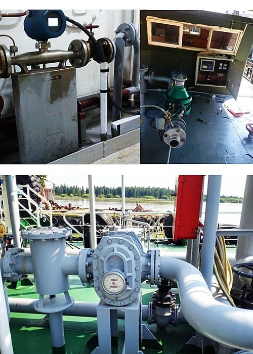
Fuel Flow Meter for Boat

At present, ships are in the process of refueling, especially for heavy fuel oil. The traditional method of measuring tank capacity is used to calculate the quantity of fuel oil. This method is very cumbersome and the accuracy is not high. And if the fuel flow meter is used, the above shortcomings can be well overcome.

There are many kinds of flowmeters on the market now, which makes it difficult for designers to choose their models. Different types of flowmeters have different characteristics. When choosing a suitable flowmeter according to the characteristics of the ship’s fuel oil, good test results can be achieved.

Instruments that measure the flow or total volume in pipe flow or open channel flow are collectively referred to as flow meters. There are many types of flow measurement methods and meters. The measuring principle, structural characteristics, scope of application and method of use are different.

Up to now, there are more than 60 types of flow meters available for industrial use. Because so far, there is no flow meter that can be used for any fluid, any range, any flow state, and any use condition.

There are many ways to classify flow meters. According to different classification principles, the classification methods are also different. Classified by principle, flow meters can be divided into three types: volumetric, velocity and differential pressure.

One of the more popular classification methods is from the measurement method and structure classification. It can be divided into: differential pressure flowmeter, positive displacement flowmeter, float flowmeter, impeller flowmeter, electromagnetic flowmeter, fluid oscillating flowmeter, ultrasonic flowmeter, mass flowmeter, plug-in flowmeter, open channel flowmeter There are 11 categories with other flow meters.

Read more about:

Precautions for flowmeter selection

  1. The performance of the flow meter

The performance of the flowmeter is embodied in the flow range, linearity, repeatability and accuracy.

The flow rate range is the range defined by the minimum flow rate and the maximum flow rate. When selecting the type, pay attention that the flowmeter cannot exceed this range under normal use conditions.

Linearity indicates the degree of consistency between the flow characteristic curve and the specified straight line in the entire flow range. According to this feature, the flowmeter output can be divided into linear and nonlinear square roots.

The non-linear error has a great influence on the pulse output type flowmeter with a large flow range. Repeatability refers to the consistency of the results obtained from multiple measurements of the same measured under the premise of the same conditions.

Generally, the higher the repeatability, the more concentrated the measurement value. Accuracy refers to the degree of agreement between the measured value and the actual value.

The lower the accuracy of the meter, the greater the error. The greater the deviation between the measured value and the actual value. When determining the accuracy, it should be selected according to the accuracy requirements of the actual measurement.

Extended Reading: Mechanical flow meter for diesel

  1. Working conditions

The working conditions that affect the flowmeter measurement mainly include temperature and electromagnetic interference.

The volumetric flowmeter uses a constant volume chamber to measure the flow rate. The material of the mechanical parts constituting the chamber is generally made of steel.

It becomes brittle when the temperature is low, and expands when the temperature is high. The pressure is limited at low temperatures.

For example, the twin-screw flowmeter in the fuel viscosity unit of the main engine on the actual ship. The rotor is often stuck during the light-to-heavy oil conversion. This is the reason.

In addition to the above and other conditions, it should be considered. Because of the particularity of the ship’s working environment, it is different from land. When choosing a flowmeter for a ship, it should also be combined with the actual working environment of the ship. Consider other factors that may affect the flowmeter. .

Ships are inevitably affected by many factors when sailing on the water, such as vibration, roll, impact, erosion, and sudden changes in climate. The operating environment is quite harsh. In order to ensure that the instrument can operate reliably and accurately in actual use, marine requirements must be considered when selecting models.

  1. Installation conditions

The installation conditions depend on the requirements of the site space and orientation. Specific instruments have special requirements. Therefore, the installation conditions should be given full attention.

For example, a positive displacement flow meter often requires the installation direction and flow direction of the sensor to be horizontal, vertical and horizontal respectively.
Positive displacement flow meters are sensitive to impurities and require filtration accuracy. Sometimes a filter device is needed. The float type flowmeter is more sensitive to the flow rate. Therefore, in order to eliminate the influence on the measurement. When limited by space, there are also flow regulators. Therefore, the space and orientation of the work site must be considered during installation.

Extended reading: Orifice Plate Flow Meter

Selection of Fuel Flow Meter for Boat

  1. Fuel performance

Fuel oil is a mixed liquid whose viscosity changes greatly with temperature, and there are many impurities in it.
Generally, when fuel oil is installed, it is realized through a closed delivery pipeline. The type of fuel generally installed on real ships is F120, and its density at 20°C is 981.6㎏/m3.

Combine these properties of fuel. Compared with the performance analysis of various flowmeters introduced above. Although volumetric flowmeters and turbine flowmeters have high accuracy, they have high requirements for fluid cleanliness. Electromagnetic flowmeters are only suitable for conductive liquids, so they are not applicable here. Coriolis mass flow meters can be used, but the cost is higher. Differential pressure flow meters are also optional. However, it is necessary to cooperate with a differential pressure transmitter for flow measurement and control.

  1. Working conditions of fuel flow meter

When the fuel flow meter is working, the temperature of the fuel passing through the flow meter is about 40°C. The agreed pump speed is 12m3/h, and the agreed maximum pump pressure is 0.4MPa. The amount of fuel added this time is 240t.

According to these few data, in the further flowmeter selection. Float flow meters should also be excluded. According to the characteristics of the float flowmeter, set up and measure the small flow of fluid. However, when the fuel is installed, the quantity is too large and it is not suitable for selection.

The vortex flowmeter works by using the principle of fluid oscillation. Avoid strong vibration when installing the sensor. However, according to the working conditions of the ship, the vibration and noise are very large. If a vortex flowmeter is selected, the measurement accuracy will be greatly affected in actual use.

It can be generally determined that both the differential pressure flowmeter and the ultrasonic flowmeter meet the requirements. Also, gear flow meters, mass flow meters, etc. These types of flow meters have a wide range of applications and are suitable for a variety of liquids.

Extended Reading: Guide and Selection for Diesel Fuel Flow Meters

Featured Fuel Flow Meter for Boat

The intelligent liquid turbine flowmeter is a new type of intelligent instrument that integrates the turbine flow sensor and display integration, which is developed by using advanced ultra-low power single-chip microcomputer technology. It has a compact structure, intuitive and clear reading, and high reliability. Not subject to external power supply. Obvious advantages such as lightning resistance and low cost.

Turbine Digital Flow Meter is widely used to measure the corrosion of stainless steel 1Cr18Ni9Ti, 2Cr13, corundum Al2O3, and cemented carbide in closed pipelines, and there is no fiber, particles and other impurities. Liquids with kinematic viscosity less than 5×10⁻⁶m2/s at working temperature, and liquids with kinematic viscosity greater than 5×10⁻⁶m2/s. The flowmeter can be used after real liquid calibration. If matched with a display instrument with special functions. It can also carry out quantitative control, over-quantity alarm, and so on. It is an ideal instrument for flow measurement and energy saving.

A Cylinder gear flow meter is a micro digital positive displacement flow meter. Can measure very small flow rates and quantify small volumes of liquid. High and low-temperature resistance (-196℃-200℃).

Cylinder Gear flow meter is a type of positive displacement flow transmitter. It is a high-precision transmitter for measuring volumetric flow. With the flow of the medium, the gears mesh and rotate. Under the action of fluid flow. Measure the number of revolutions of the gear to know the flow of liquid and liquid flowing through the instrument. It is especially suitable for the flow measurement of heavy oil, polyvinyl alcohol, grease, and other high-viscosity media. It can measure the viscosity of Fluid up to 10000Pa.s.

Oval gear flow meter is one of the typical positive displacement flow meters. Measure the flow of liquid filling the pipeline under a certain pressure.

Oval gear flow meter is a pointer display type positive displacement flowmeter. The word wheel accumulates counting, and can be equipped with a zero return device. Oval gear flowmeters are widely used in liquid flow control in various industrial fields. Applicable to various types of liquid measurement, such as crude oil, diesel, gasoline, etc. Choose different manufacturing materials, such as crude oil, diesel, gasoline, etc. can be measured.

PD Flow Meter is referred to as positive displacement flowmeter. Helical Gear-PD Flow Meter is also called, spiral double rotor flowmeter, LLT, LZ double rotor flowmeter or UF-Ⅱ spiral rotor flowmeter.

As a high-precision flow meter, PD Flow Meter has an accuracy of 0.2 level. It is especially suitable for the measurement of industrial liquids such as crude oil, refined oil and light hydrocarbons. It is a new generation volumetric flowmeter. Because it uses a pair of spiral rotors with special teeth, it is also called “Helical Gear Flowmeter”.

Marine Fuel Mass Flow Meter (MFM)

Mass flow meter directly measures the mass flow of the medium passing through the flow meter. It can also measure the density, temperature and viscosity of the medium

The Singapore Standards Committee issued the new Singapore Standard SS6481-Marine Fuel Mass Flow Meter (MFM) Usage Guidelines. To support the shipping industry’s formal implementation of the “Sulfur Restriction Order” from January 1, 2020 to improve the low-sulfur fuel system. And Guidelines for improving and regulating MFM fuel filling behavior.

Regarding Singapore’s new SS6481-Marine Fuel Mass Flow Meter (MFM) Code of Conduct. The Director of the Technical Committee for Bunkering (Chairman, Technical Committee for Bunkering) Seah Khen Hee pointed out——
“Metrology and system integrity are the dual foundations of SS648. It is the foundation of MFM system approval and fuel metering and handover procedures.”

Extended reading:

Singapore launches enhanced mass-flow metering standard

Sino-Inst, Manufacuturer for Fuel Flow Meter for Boat. For example: crude oil flowmeter, diesel flowmeter, gasoline flowmeter.

Sino-Inst’s Fuel Flow Meter for Boat, made in China, Having good Quality, With better price. Our flow measurement instruments are widely used in China, India, Pakistan, US, and other countries.

Request a Quote

Please enable JavaScript in your browser to submit the form

Guide for Digital Fuel Flow Meter

Digital Fuel Flow Meter is a flow meter dedicated to measuring fuel, diesel, gasoline, and petroleum. Digital Fuel Flow Meter generally has a digital display or signal output. Such as pulse or 4-20mA. Such as turbine flow meters, gear flow meters. It can be used to measure the pipeline flow of oil medium storage, transportation, trade, etc. Different pipelines and working conditions require flow meters with different principles or functions. Next, we will analyze in detail.

The digital diesel fuel flow meter comes with a large LCD display which is convenient for clear reading.
Another display method of Diesel fuel flow meter is the dual display of pointer and word wheel instantaneous cumulative count. Now it also supports electronic digital display, which makes the instantaneous and cumulative flow more intuitive. In the case of electronic digital display flowmeter mode, it can also realize the on-site online data remote transmission function to support different signal output modes. The pointer plus the word wheel display and the electronic digital display can be applied to more on-site working conditions and are widely used and recognized.

Extended reading: Fuel Flow Meter for Boat-Selection & Application

As a commonly used energy source in industrial production, diesel oil needs to be metered in many occasions. For pipeline transportation of oil tankers or diesel storage tanks, it is more suitable to select a flow meter with higher measurement accuracy to measure. Because not only to facilitate trade settlement. And it needs to be accurate. The measurement is accurate. Can be used for a long time.

The intelligent liquid turbine flowmeter is a new type of intelligent instrument that integrates the turbine flow sensor and display integration, which is developed by using advanced ultra-low power single-chip microcomputer technology. It has a compact structure, intuitive and clear reading, and high reliability. Not subject to external power supply. Obvious advantages such as lightning resistance and low cost.

Turbine Digital Flow Meter is widely used to measure the corrosion of stainless steel 1Cr18Ni9Ti, 2Cr13, corundum Al2O3, and cemented carbide in closed pipelines, and there is no fiber, particles and other impurities. Liquids with kinematic viscosity less than 5×10⁻⁶m2/s at working temperature, and liquids with kinematic viscosity greater than 5×10⁻⁶m2/s. The flowmeter can be used after real liquid calibration. If matched with a display instrument with special functions. It can also carry out quantitative control, over-quantity alarm, and so on. It is an ideal instrument for flow measurement and energy saving.

Most widely used types are mechanical and digital inline fuel meters. Differential flow sensors are available. Like: the turbine, positive displacement (oval gear), Coriolis, and differential pressure flow meters.

Sino-Inst offers a variety of fuel flow meters for most fuels. Including diesel, bio-diesel, kerosene, gasoline, oil, heating oil, grease, and certain chemicals. Sino-Instrument offers diesel fuel flow measurement solutions and free technical support. If you have any questions about diesel fuel flow measurement, please contact us.

Marine fuels mainly include light diesel, heavy diesel, fuel oil, and residual fuel oil.

To put it simply, if the tested marine fuel is a low-viscosity, clean fuel. Then you can choose a turbine flowmeter. The price is reasonable and the measurement is stable.

If the marine fuel being tested is heavy oil, high-viscosity fuel. Then it is recommended to choose an oval gear flowmeter.

If the measured marine fuel is a small flow rate. Then it is recommended to use a circular gear flowmeter for measurement.

If the tested marine fuel has impurities. It is recommended to install a filter before the flowmeter.

If you still do not know how to choose the right marine fuel flow meter. You can contact our sales engineer. We will provide you with a suitable marine fuel flow measurement program.

Read more about Large-diameter Oval Gear-Marine Fuel Flow Meter

Volumetric Flow Meter, as a mechanical flow meter, is also called Positive displacement flowmeter. It can measure the volume flow of high viscosity and corrosive fluids.

Volumetric Flow Meter is a mechanical instrument used to measure the volume flow of fluids. A volumetric flow meter is an instrument which can measure either directly or indirectly the volume of a substance which is passing through a specific location in a set period of time. The main advantage of these types of flow meters is that they can handle high viscosity and corrosiveness fluid.

Extended Reading: Magnetic Battery Operated Flow Meter

Electronic flow meters are industrial digital flow meters for fluid flow rate measurement. In more cases, people will default that Electronic flow meters are electromagnetic flowmeters.

Electronic flow meters types like Magnetic, Vortex, and Ultrasonic flow meters. Electronic flow meters are suitable for Industrial liquid, water, natural gas, petrol, fuel, air, and more fluid flow. Electronic flowmeters convert the monitored fluid flow into electronic signals. Including pulse signal, 4-20mA standard signal, etc.

Sino-Inst offers a variety of  Electronic flow meters for flow measurement. If you have any questions, please contact our sales engineers.

There is also a compact electronic turbine flowmeter.
It is widely used for small-caliber measurements of gasoline, diesel, water, methanol, alcohol, etc.

Extended Reading: Petroleum Flow Meter

GPI is a registered trademark of Great Plains Industries, Inc. of the United States. It has been producing turbine and oval gear flow meters for more than 30 years.

The headquarters of American GPI is located in Wichita, Kansas, USA. It is a global professional manufacturer of fluid transportation and measurement. Relying on its strong product development capabilities and complete turbine and elliptical gear flowmeter production lines and product testing lines. After more than 30 years of development, it has won the support and trust of more and more customers around the world.

In China, GPI products have been widely used in the chemical, oil, pharmaceutical, food and beverage, water treatment, and automotive equipment manufacturing industries.

GPI mainly produces two categories of products:
▲ GPI turbine flowmeter, oval gear flowmeter;
▲ GPI fluid delivery and storage system, including manual pumps, electric pumps, etc.

Extended Reading: Fuel Flow Meters for Diesel-Marine fuel-Industrial oil

Featured Digital Fuel Flow Meters

How to Choose the Right Digital Fuel Flow Meter?

There are many types of flow meters on the market, and the prices are different. There are so many brands at home and abroad, it is easy to get confused. So how should we choose the right flow meter?

To put it simply, we should start from the actual measurement conditions when choosing a flow meter. Combine installation requirements, monitoring requirements, and budget costs. In order to choose the most suitable Digital Fuel Flow Meter for you.

  1. Look at the condition of the fluid. Including fluid viscosity, corrosivity, etc. For example, for high-viscosity oils, gear flow meters are recommended. For low viscosity, turbine flowmeters can be used.
  2. Flow rate range. Minimum flow, maximum flow. Common flow.
  3. Pipeline diameter. The inner diameter, outer diameter, wall thickness, etc. of the pipe. Determine the caliber of the flowmeter according to the flow rate and the size of the industrial pipe. Generally, the flow meter that is consistent with the pipeline is selected. If the flow range does not meet, then operations such as necking can be considered.
  4. The temperature of the medium. For example, in the case of ultra-high temperature, the material and structure of the flow meter need to be changed.
  5. Pipeline pressure. Select the pressure level of the flanges connected on both sides according to the pressure level of the process pipeline. According to the different materials of the flowmeter in contact with the liquid, the pressure resistance is different, and the pressure resistance range of stainless steel and copper is larger. If the flow rate is relatively low, pressure loss needs to be considered. In this case, turbines and positive displacement flow meters are not suitable.
  6. Signal output. If signal output is not required, rotameter and mechanical water meter are generally sufficient. The output signal has analog quantity (4-20ma, 0-10 v) and pulse output, these flowmeters can have digital display.
  7. Accuracy requirements.
  8. Installation conditions. Some flow meters have strict requirements for straight pipe sections. Need to be considered in advance.
  9. Budget cost.
  10. Maintenance.

If you sort the above parameters, you don’t know which flowmeter you should choose. Then, you can contact Sino-Inst sales engineer. We will select the appropriate digital fuel flow meter according to your requirements.

Extended Reading: Guide and Selection for Diesel Fuel Flow Meters

Frequently
Asked
Questions

Different digital flow sensors include turbine, thermal mass, electromagnetic, ultrasonic, orifice plate, venturi. The different designs of the flowmeters have a variety of applications. With 4-20ma, RS485, or other output.

Then they all work differently. However, they can convert the flow signal into a digital display, or pulse, or 4-20mA signal.

Extended reading: Ultrasonic Flow Meters Types & Technical Guide

What is a fuel flow meter? The fuel flow meter is an instrument that can monitor fuel flow. Industrial Fuel is an important energy source. For example, diesel, marine fuel, gasoline, etc.

Extended Reading: Mechanical oil flow meter

A diesel Flowmeter is a kind of positive displacement Meter to measure the liquid flow or instantaneous flow of the Pipe tube. lt is a kind of accumulated meter. With Characteristics of high accuracy, small change by the fluid Viscosity, it is widely used to measure oil kind liquid, forbidden to measure corrosive.

Extended reading: More Inline Digital Diesel Fuel Flow Meters

Currently, the digital flow meters provided by Sino-Inst support flange installation, threaded installation, plug-in installation or external clamp installation. Different flow meters have different installation requirements.

Extended reading: Orifice Plate Flow Meter

Sino-Inst, Manufacuturer for Digital Fuel Flow Meters. For example: crude oil flowmeter, diesel flowmeter, gasoline flowmeter.

Sino-Inst’s Digital Fuel Flow Meters, made in China, Having good Quality, With better price. Our flow measurement instruments are widely used in China, India, Pakistan, US, and other countries.

Request a Quote

Please enable JavaScript in your browser to submit the form

Water Level Monitoring Sensor/System for Sewage-Wastewater

Water Level Monitoring Sensors can be used to detect changes in water level. The Water Level Monitoring Sensor and other control equipment work together to form the Water Level Monitoring System. The Water Level Monitoring Sensor/System is used to monitor the discharge of industrial wastewater and urban sewage. This is the development direction of smart cities. Let’s talk about Water Level Monitoring Sensor/System for Sewage-Wastewater in detail below.

Level monitoring

By installing a drop-in liquid level monitoring box at the head of the sewage well. Real-time monitoring of liquid level data of sewage wells. The monitoring data is uploaded to the platform through wireless communication. The cloud platform recognizes anomalies based on data statistical algorithms.

When the liquid level exceeds the set alarm threshold, the system will send an over-limit alarm. Notify relevant personnel to start the pump to drain water. When the level detector has equipment failure. Record the fault alarm. Notify relevant personnel to inspect the equipment.

Extended reading: Float Level Sensors – Single and Multipoint

Surface Water Level Monitoring is suitable for the water department to monitor the surface water level. At the same time, it supports remote image monitoring. Provide accurate and timely on-site information to ensure proper water storage and safe flood season.
It is helpful for the Water Affairs Bureau to grasp the current situation of water resources in the region, the use of water resources, strengthen the recovery of water resources fees, and achieve the purpose of correct evaluation, reasonable dispatch, and effective control of water resources.

  1. Remote monitoring function. It can remotely monitor real-time data such as water level, rainfall, field equipment operating status, equipment voltage and so on.
  2. Remote control function. The opening/closing of the reservoir valve can be remotely controlled in the center according to the height of the on-site water level to maintain the normal water level.
  3. Image monitoring function. An external camera can be connected. Live photos can be taken. The photos can be uploaded to the monitoring center. The staff on duty can understand the situation on the spot without leaving home. Support regular and manual photos.
  4. Automatic alarm function. It will automatically alarm if the water level exceeds the limit, the rainfall exceeds the limit, the equipment fails, and the door is opened abnormally.
  5. Automatic statistics function. According to historical data, automatic statistics into daily reports, monthly reports, annual reports, etc.. Generate analysis charts according to customer needs.
  6. Data storage function. The monitoring center and the field terminal can store historical data bidirectionally. It can store not less than 10 years of historical data.

Scope of application:

  1. River water level monitoring. Real-time monitoring of the water level of the river provides a basis for decision-making.
  2. Lake water level monitoring. The required information can be extracted by uploading real-time water level conditions.
  3. Water level monitoring of the reservoir. Real-time monitoring of the water level in the reservoir is convenient for timely water replenishment and does not affect production and life.
  4. The upstream and downstream water level monitoring of the reservoir. The water level changes of the upper and lower water levels can be reflected through the water level gauges of various manufacturers.
  5. Rainfall monitoring in the reservoir area. Rain gauge measurement is used as the basis for rainfall and rainfall intensity in the reservoir area.
  6. On-site picture monitoring of the reservoir. Industrial cameras upload on-site pictures of the reservoir area.
  7. Monitoring of the infiltration line of the dam of the reservoir. Observe the position of the infiltration line of the dam body by embedding a piezometer.
  8. Monitoring the seepage pressure of the dam foundation of the reservoir. The seepage pressure distribution of the dam foundation is reflected by the embedded piezometer.
  9. Reservoir dam displacement monitoring. Accurately understand the horizontal and vertical deformation of the dam surface.

Extended reading: Radar Water Level Sensor Applied To River/Reservoir Monitoring

The river water level monitoring system is suitable for the water management department to remotely monitor the water level, rainfall, and other real-time data of the river basin. At the same time, it supports remote image monitoring. It provides accurate and timely on-site information to ensure proper water storage and safety in the river basin.

The river water level monitoring system achieves real-time monitoring of water and rain conditions and realizes the information management of the river. It has played a major role in protecting people’s lives and property safety.

System Overview

The river water level monitoring system is an important method for real-time control of river water regime changes, scientific early warning of flood disasters, improvement of flood control command capabilities, and reduction of rain and flood disaster losses.

System functions

  • Real-time monitoring of river water level, can expand rainfall, water quality, flow rate monitoring.
  • Support remote camera or video real-time monitoring (depending on the communication method).
  • When the water level exceeds the limit, the sensor fails, and the battery voltage of the monitoring terminal is low, the alarm will be immediately alarmed.
  • Automatically generate water level process curve and data statistics report.
  • It can be linked with the drainage pump station to automatically control the start and stop of the drainage pump group according to the water level of the river.
  • Supports docking with other comprehensive monitoring application platforms through OPC, database and other forms.

System Features

  • Strong compatibility: Compatible with various types of water level gauges such as ultrasonic, radar, float, laser, bubble, and drop-in type.
  • Flexible form of power supply: According to site conditions, it can be flexibly selected to supply power to the equipment by means of city electricity, solar energy, batteries, etc.
  • Various communication methods: support GPRS, CDMA, NB-IOT, short message, Beidou satellite, 3G/4G, WIFI, ADSL/optical fiber and other communication methods.

Extended Reading: GWR Level Sensor for High Temperature & High Pressure

The water level control switch is a feedback liquid level position signal. It informs the center console of the duty room whether the water level has reached the specified water level. It can also control the startup or shutdown of related equipment (such as water pumps). The signal voltage is often a safety voltage of 12V or 24V.

Water Level Control Sensor Switch is widely used in industrial boilers, civil construction pools, water towers, water tanks. As well as open or closed storage tanks in petrochemical, paper, food, sewage treatment, and other industries. Level measurement of various liquids in underground tanks. The tested medium can be divided into various conductive and non-conductive liquids such as water, oil, acid, alkali, industrial sewage, and so on. It forms a set of advanced liquid level display and control equipment with the electric valve, which automatically opens and closes the electric valve.

Extended reading: RF Admittance Level Sensor

Tank level sensor is a common sensor for measuring liquid level position. It converts the height of the position into an electrical signal for output. The liquid level sensor is a modular circuit. It has the advantages of acid resistance, moisture resistance, shock resistance, and corrosion resistance. The circuit contains a constant current feedback circuit and an internal protection circuit. The maximum output current can be made to not exceed 28mA. Therefore, the power supply can be reliably protected and the secondary meter is not damaged. In general, it is used in electrical appliances and equipment that require water level control.

Read more Tank Level Gauges & Indicators.

We can divide Water Level Sensors into two categories by measuring whether they are in contact with the water level.

One type is contact type. Including single flange static pressure/double flange differential pressure level transmitter, float type level transmitter, magnetic level transmitter, input type level transmitter, electric internal float level transmitter Sensors, electric float level transmitters, capacitive level transmitters, magnetostrictive level transmitters, service level transmitters, etc.

The second category is non-contact. Divided into the ultrasonic level transmitter, radar level transmitter, and so on.

Extended Reading: Chilled Water Flow Meter

Ultrasonic liquid level Sensor adopts an ultrasonic pulse-echo method to realize liquid level measurement. Specifically, the transducer (probe) of the ultrasonic liquid level Sensor sends out high-frequency ultrasonic pulses. When it encounters the surface of the liquid level to be measured, the sound wave is reflected back. Part of the reflected echo is received by the transducer (probe) and converted into an electrical signal. The user can know the water level almost in real-time based on the reflected signal.

When choosing a water level measuring instrument, it is recommended to measure the ultrasonic liquid level Sensor here. It adopts microprocessor program control technology and intelligent signal processing technology. The measurement is efficient and accurate.

Read more about: Common River Water Level Measurement Methods

The protection level of the whole machine is as high as IP66/IP67, which can effectively prevent dust from inhaling, and can be immersed in water for a short time. At the same time, the probe is made of high explosion-proof grade (Ex d IIC T6 Gb) and PVDF material. It is very suitable for applications in harsh and noisy outdoor environments with corrosive liquids, harsh working conditions, and strong interference.

In addition, the ultrasonic liquid level Sensor has a variety of ranges to choose from. The longest can be measured at 15 meters. Very suitable for long-distance detection and tank level detection.

In addition to the use of ultrasonic level Sensors for water level monitoring. Users can also use radar, depth water level sensors, and other technologies to monitor the water level. Instead, use an ultrasonic liquid level. It is a liquid-level measuring instrument with a low maintenance cost and wide application range at present. Users can accurately obtain all required data. And with high-cost performance, it is favored by the majority of users.

Extended reading: Hydrostatic Level Measurement

Featured Water Level Monitoring Sensors

Wastewater/sewage pipe network flow and liquid level online monitoring solution

The online monitoring system for the flow and liquid level of the drainage/sewage pipe network is an important part of the intelligent drainage construction in Anhui. Through this system, the management department can globally grasp the operating status of the drainage pipe network, effectively identify the silting pipe section, and discover the abnormality of the manhole cover in time. In order to quickly respond to flood prevention and protect residents’ travel safety.

On-site monitoring equipment composition:

  • Well monitoring RTU: battery-powered, IP68 waterproof RTU
  • Water level detection equipment: drop-in level gauge (ultrasonic level gauge and other level gauges can also be used)
  • Manhole cover status detection equipment: travel switch (limit switch)

System implementation instructions

1) The limit switch is installed under the manhole cover. When the manhole cover was closed, it just touched the contact of the travel switch. When the manhole cover is moved, the contact state of the limit switch changes. Such as from “open” to “closed”. And output this state change signal to the manhole monitoring RTU through the cable.

2) The probe of the throw-in water level gauge is installed at the bottom of the manhole and fixed firmly. Real-time detection of water level data in the manhole. And output the data to the manhole monitoring RTU through the cable.

3) Under normal circumstances, the well monitoring RTU regularly (time interval can be set) transmits the status and water level data of the well cover to the monitoring center through the GPRS/CDMA/4G/NB-IoT network. When the state of the manhole cover changes or the water level data exceeds the preset alarm value. The well-monitoring RTU reports alarm information to the monitoring center in real-time.

4) The center’s drainage pipe network monitoring system software dynamically displays the water level data and manhole cover status of each manhole. It provides query, statistics, and analysis functions, and prompts alarm information in various forms such as pop-up windows, prompt sounds, and short messages.

System functions

  • Monitor the water level of the wells at the important nodes of the pipeline network, and detect the siltation and blockage of the pipeline network in time.
  • Monitor the status of the manhole cover, and immediately alarm when the manhole cover is lost or displaced.
  • Provide timely warning information on the operation of the pipeline network to provide a decision-making basis for emergency flood prevention work.
  • Diagnose the bottleneck pipe section in the drainage pipe network, and provide a basis for the pipe network transformation.
  • Provide analytical data for evaluating the drainage capacity of low-lying and flood-prone areas.
  • Trace the historical status of the pipeline network operation to assist in accident analysis.

Extended reading: Radar Level Sensor Working Principle

Water Level Sensor Working Principle

The function of the water level sensor is to detect the water level. The water level sensor is widely used in electrical appliances and industrial equipment that require water level control. The water level sensor can realize the function of water shortage protection.

Principle of water level sensor:
The water level sensor has a sensor. Transform the sensed water level signal into a current signal.

There are many types of water level sensors, so their specific measurement principles are different.
If you need to learn more. You can refer to:
Differential pressure type liquid level measuring instrument;
Float level measuring instrument;
Electric liquid level measuring instrument;
Ultrasonic liquid level measuring instrument;
Radar liquid level measuring instruments, etc.

Extended reading: Capacitive water level sensor

More level measurement solutions

List of Radar Level Sensors

Non-contact radar level sensor Radar level sensors are used for continuous non-contact level measurement of liquids or solids. And…

Capacitive Fuel Level Sensor

The capacitive fuel level sensor refers to a capacitive liquid level transmitter used to measure the oil level. According…

Frequently
Asked
Questions

If it is just an ordinary tank or well water level measurement. Then our first choice is the hydrostatic pressure submerged liquid level sensor. Also called hydrostatic level sensors.

Because of its lowest cost. Installation, use and maintenance are very simple.

Extended reading: Float Switch Water Level Controller

Accurately measure the water level. In turn, the water level can be better controlled within the allowable range. It is of great significance to ensure safety and improve economic efficiency.
for example:
Many types of equipment in thermal power plants need to maintain a normal water level in order to operate safely and economically.
For example, boiler drum water level, deaerator water level, steam turbine condenser water level, high and low-pressure heater water level, etc.

Extended Reading: FMCW Radar for High Temperature Level Sensor

Extended Reading: Wireless Water Meter

Sino-Inst offers over 50 Water Level Monitoring sensors/Systems for Sewage-Wastewater. About 50% of these are Radar level meters, 40% is magnetic level sensor.

A wide variety of Tank Level Gauges & Indicators for Water Level Monitoring sensors/Systems for Sewage-Wastewater options are available to you, such as free samples, paid samples.

Sino-Inst is a globally recognized supplier and manufacturer of Water Level Monitoring Sensor/System for Sewage-Wastewater instrumentation, located in China.

Request a Quote

Please enable JavaScript in your browser to submit the form

The Myth of Ceramic Pressure Sensor

What is a ceramic pressure sensor?

Ceramic pressure sensors are sensor diaphragms made of ceramic alumina (Al2O3). Ceramic is a material with high elasticity, corrosion resistance, wear resistance, impact, and vibration resistance. Ceramic has good thermal stability characteristics. High-temperature sintering process for the thick film. The working temperature range of the ceramic pressure sensor is as high as -40~125℃. The high elasticity and creep resistance of ceramics. The ceramic pressure sensor has good long-term stability. Besides, the corrosion resistance of ceramics. It has advantages in the fields of refrigeration, chemical industry, and environmental protection.

The Basic Structure of Ceramic Pressure Sensor

The ceramic pressure sensor is mainly composed of a ceramic ring, a ceramic diaphragm and a ceramic cover plate.
The ceramic diaphragm acts as a sensitive elastic body. It is made of 95% AL2O3 porcelain. It is required to be flat, uniform and dense. Its thickness and effective radius depend on the design range.

The porcelain ring is shaped by high-temperature firing using a hot die-casting process. High-temperature glass slurry is used between the ceramic diaphragm and the ceramic ring. It is fired together by thick film printing and thermal firing technology. It forms a cup-shaped elastic body with a fixed peripheral edge. That is, a non-creep rigid structure should be formed in the fixed support part of the ceramic periphery.

On the upper surface of the ceramic diaphragm, which is the bottom of the porcelain cup. The circuit of the sensor is made with thick film technology. The circular groove at the lower part of the ceramic cover creates a certain gap between the cover and the diaphragm. The limit can prevent the diaphragm from rupturing due to excessive bending when it is overloaded. Form the anti-overload protection of the sensor.

Extended reading: Common Pressure Sensor Applications

Featured SI-338 Ceramic Pressure Sensor

SI-338 Ceramic pressure sensor uses ceramic or diffused silicon core. All stainless steel package, small and beautiful appearance. Suitable for occasions with limited installation space. Wide range temperature compensation, high accuracy, small size, no adjustment, wide range coverage. Support OEM processing. Ceramic pressure transmitter is used in compressor, air conditioning and other pressure measurement.

Extended reading: What Is Flush Diaphragm Pressure Sensor?

Features of Ceramic Pressure Sensor

Ceramic is a recognized material with high elasticity, corrosion resistance, wear resistance, impact and vibration resistance. The thermal stability of ceramics and its thick film resistors can make its operating temperature range as high as -40 to 135°C. It also has high accuracy and high stability for measurement. Electrical insulation degree>2kV. Strong output signal. Good long-term stability.

Ceramic sensors with high characteristics and low prices will be the development direction of pressure sensors. In Europe and the United States, there is a trend to completely replace other types of sensors. In China, more and more users use ceramic sensors to replace diffused silicon pressure sensors.

  • Ceramic sensitive diaphragm with high overload capacity;
  • Zero point and full scale laser calibration;
  • Excellent anti-corrosion and anti-wear performance;
  • Anti-shock and anti-vibration;
  • High precision and high stability;
  • Wide operating temperature range;
  • Small size, easy to package;
  • Environmental friendly;

Extended reading: What is a pressure sensor?

Ceramic Pressure Sensor Working Principle

The corrosion-resistant ceramic pressure sensor has no liquid transmission. The pressure directly acts on the front surface of the ceramic diaphragm, causing the diaphragm to produce a small deformation.

The thick film resistor is printed on the back of the ceramic diaphragm. Connected to form a Wheatstone bridge (closed bridge).

Due to the piezoresistive effect of the varistor, the bridge generates a highly linear voltage signal proportional to the pressure and proportional to the excitation voltage. The standard signal is calibrated to 2.0 / 3.0 / 3.3 mV/V according to the pressure range. Etc. Compatible with strain gauge sensors.

Calibration by laser. The sensor has high temperature stability and time stability. The sensor comes with a temperature compensation of 0~70℃. It can be in direct contact with most media.

Extended Reading: Up to 800°C High Temperature Pressure Sensor

Ceramic Pressure Sensor Types

The base material of ceramic pressure sensor is Al2O3 ceramic. According to the principle of realization, it can be divided into capacitive pressure sensor and piezoresistive pressure sensor.

The ceramic substrate and diaphragm are plated with metal and used as electrodes. The two ceramic parts are connected together by a glass seal. Maintain a controllable gap. So that the two metal electrodes form a capacitor.

If pressure is applied. Then the gap between the substrate and the diaphragm will be changed. Thereby changing the capacitance of the sensing element. The pressure-related signal output is formed by the subsequent processing circuit.

Because the edge of the ceramic diaphragm is fixed on the ceramic base. Peripheral support. When the force is applied, the middle deformation becomes larger, and the edge becomes smaller. The capacitance produces nonlinearity and reduces sensitivity.

In order to reduce temperature effects and edge effects. In the design, a circular single electrode is set on the ceramic diaphragm as the common electrode. Two electrodes are arranged on the ceramic cover plate to equalize the area. It forms a coaxial ring-shaped dual-capacitance sensor.

Extended Reading: MEMS Pressure Sensors

The center is the measurement capacitance Cp. The edge ring is the reference capacitor Cr. The outside of Cr is the fixed side. The subsequent signal conditioning circuit deals with the voltage difference between the two capacitors. The change of Cp and Cr is converted into DC voltage output by using square wave excitation signal. The magnitude of the applied pressure is measured by the difference signal of the two output voltages.

The dual-capacitor structure greatly reduces the nonlinear error of the sensor system. At the same time, when the ambient temperature changes, the two capacitors experience the same temperature change. The temperature effect of temperature on them is consistent. This offsets the measurement error caused by temperature changes. Realize the function of temperature self-compensation.

Extended reading: Featured Diaphragm Seal Pressure Transmitters

The piezoresistive pressure sensor is mainly composed of a ceramic ring, a ceramic diaphragm and a ceramic cover plate.

The ceramic diaphragm acts as a sensitive elastic body. On it, a thick film process technology is used to form a Wheatstone bridge as the sensor circuit. Due to the piezoresistive (deformation) effect of the resistor, a voltage signal is generated.

The thick film resistor is printed on the back of the ceramic diaphragm. Connected as a Wheatstone bridge (closed bridge).

When the pressure is zero. The bridge is in a balanced state, and the output voltage is zero.

When pressure is applied to the bridge. The deformation of the diaphragm causes the resistance of the four resistors of the bridge to change. The bridge is in an unbalanced state. Generate a highly linear voltage signal proportional to the pressure and proportional to the excitation voltage.

Due to the piezoresistive (deformation) effect of the resistor, a voltage signal is generated.

The standard signal is calibrated to 2.0 / 3.0 / 3.3 mV/V etc. according to the pressure range. Compatible with strain gauge sensors.

Calibration by laser. The sensor has high temperature stability and time stability. The sensor comes with a temperature compensation of 0~70℃. And can be in direct contact with most media.

Extended reading: Silicon Pressure Sensor

Frequently
Asked
Questions

There are many types of pressure sensors. Such as resistance strain gauge pressure sensors, semiconductor strain gauge pressure sensors, piezoresistive pressure sensors, inductive pressure sensors, capacitive pressure sensors, resonant pressure sensors, etc.

Extended reading: wireless pressure transmitter working principle

Currently, the most widely used pressure sensors include:

  • Diffused silicon piezoresistive pressure sensor,
  • Ceramic piezoresistive pressure sensor,
  • Sputtering thin film pressure sensor,
  • Capacitive pressure sensor,
  • Sapphire pressure sensor with high temperature resistance.
  • But the most widely used is the piezoresistive pressure sensor, which has a very low price, high accuracy and good linearity.

Extended Reading: Electronic Pressure Switch for Air Compressor

The piezoresistive pressure sensor is constructed using the piezoresistive effect of single crystal silicon. A single crystal silicon wafer is used as an elastic element, and an integrated circuit process is used on the single crystal silicon membrane. A group of equivalent resistors are diffused in a specific direction of the single crystal silicon, and the resistors are connected into a bridge circuit. The single crystal silicon wafer is placed on Sensor cavity. When the pressure changes, the single crystal silicon produces strain, so that the strain resistance directly diffused thereon changes proportional to the measured pressure. Then the bridge circuit obtains the corresponding voltage output signal.

Extended reading: How do you calibrate a smart pressure transmitter?

Differential pressure sensor, as the name suggests, is a kind of sensor. But it is used to transmit pressure difference. So it is called differential pressure sensor.

Generally speaking, its function is mainly to measure the difference between two different pressures. And it is displayed by the sensor. The differential pressure sensor is often used to measure the pressure of the two end points before and after a certain part of a device Difference.

Extended reading: Miniature Pressure Switch

Extended Reading: Selection of pressure transmitter

Ceramic Pressure Sensor Cost

Ceramic Pressure Sensor has low cost. The price of the ceramic pressure transmitter that people often choose is basically between USD15~35. Save a lot of costs for customers.

Extended reading: extrusion melt pressure transducer

Sino-Inst offers Ceramic Pressure Sensors. A wide variety of Ceramic Pressure Sensors options are available to you. Such as free samples, paid samples. 

Sino-Inst is a globally recognized manufacturer of Ceramic Pressure Sensors, located in China. Sino-Inst sells through a mature distribution network that reaches all 30 countries worldwide. 

Pressure sensors products are most popular in Europe, Southeast Asia, and Mid East. You can ensure product safety by selecting from certified suppliers. With ISO9001, ISO14001 certification.

Request a Quote

Please enable JavaScript in your browser to submit the form

Static Pressure/Hydrostatic Pressure Transmitter

The Hydrostatic Pressure Transmitter measures the hydrostatic pressure exerted by a hydrostatic head. Use these hydrostatic pressure transmitters to measure the liquid level in storage tanks, processing vessels, collection tanks, pump inlet heads. And other applications use hydrostatic pressure to determine the liquid height. The pressure transmitter used to measure liquid level can be called: pressure liquid level transmitter. It is mainly used for open non-pressure vessels. One is submersible type, and the other is flat film installation.

You may often hear Hydrostatic Pressure Transmitter or static pressure transmitter. So are they the same? What is their role? Next, the Sino-Inst engineer will take you to take a look.

Static pressure refers to the pressure on the surface of an object when it is stationary or moving in a straight line at a constant speed. The unit is pa. Static pressure plus dynamic pressure equals total pressure.

Static pressure pile construction is a pile-driving process in which the pile driver’s own weight and the counterweight on the frame provide reaction force through the pile driving mechanism of the static pile driver to press the pile into the soil. This kind of pile driving method completely avoids the vibration, noise, and pollution caused by hammering pile driving. Therefore, it has the advantages of no noise, no vibration, no impact, no pollution, etc. during construction.

Advantages: no noise, no vibration, no impact
Field: Fluid Dynamics

  1. The pressure generated by the fluid when it is at rest.
  2. The pressure perpendicular to the direction of fluid movement generated by the fluid when it flows.
  3. The gauge pressure value measured in a fluid that is not affected by the flow rate.

Extended reading: Static pressure vs dynamic pressure vs total pressure

Static pressure conversion table

Pa
mmH2O
inH2O
mmHg
Kgf/cm²
Atm
Bar
1bf/in²
1
0.10197
4.017mili
7.5mili
10.197u
9.869u
10u
14.5mili
9.30665
1
39.39mili
73.553mili
100u
96.78u
98.08u
1.422mili
249
25.4
1
1.8683
2.54mili
2.46mili
2.48mili
36.1mili
133.228
13.5947
0.535
1
1.359mili
1.3158mili
1.3332mili
19.337mili
98.0665k
10k
393.7
735.53
1
`0.9673
0.930665
14.2231
101.325k
10.332k
407.1
760
1.03323
1
1.01325
14.6960
100k
10.197k
401.8
750
1.01972
0.986923
1
14.5038
6.895k
703.1
27.686
69.61
70.31mili
63.05mili
63.95mili

1in=25.4mm ; 11b=445g ; k=1000; mili=0.001 ; u=0.00000

Extended Reading: Electronic Pressure Switch for Air Compressor

Hydrostatic pressure is the pressure exerted on an object by a homogeneous fluid. This is a kind of Omni-directional force, and it is evenly applied to all parts of the surface of the object. The increase in hydrostatic pressure will reduce the volume of the stressed object, but will not change its shape.

The pressure on the rock deep inside the earth’s crust is similar to this. It comes from the overlying rock layer and is called lithostatic pressure. There is also strong pressurization of the capacity load of water.

Extended reading: Industrial Pressure Transmitters|Buy from the manufacturer

Hydrostatic level measurement is often used for tank level measurement. Hydrostatic level measurement is one type of continuous level measurement.

Hydrostatic level measurement is based on the principle that the Hydrostatic is proportional to the height of the liquid. Hydrostatic submersible pressure level transmitter is the most commonly used level measurement sensor. Of course, the differential pressure transmitter can also measure the liquid level. A hydrostatic level sensor is a submersible pressure transmitter that has a pressure diaphragm at the end of level probe. A hydrostatic level sensor is a submersible pressure transmitter that has a pressure diaphragm at the end of level probe. This Hydrostatic is caused by the weight of the fluid on top of the transmitter and is used to calculate the level. And the inner side of the diaphragm is vented to atmospheric pressure.

Extended reading: wireless pressure transmitter working principle

Featured Static Pressure/Hydrostatic Pressure Transmitters

Hydrostatic Level Measurement Calculation

Liquid level sensors based on hydrostatic liquid level measurement usually measure the filling height of the container according to the following principles:

The liquid passes its specific gravity and gravity. The gravity increases with the filling height. This kind of gravity, which increases with the increase of the filling height, is called a liquid column.

So, if a static pressure type liquid level sensor is selected. This transmitter will measure the corresponding height of gravity of the liquid column as the hydrostatic pressure. Based on the measured hydrostatic pressure and product density. Now you can also calculate the filling height of the container.

Extended reading: What is flush diaphragm?

Hydrostatic level measurement has enjoyed a high reputation for many years and represents 40% of the market share. It is by far the most common electronic liquid level measurement method. Most importantly, it is well known for its high reliability and low installation cost. Therefore, users think that hydrostatic level measurement is very simple and powerful.

Extended reading: Silicon Pressure Sensor

Hydrostatic Level Transmitter Advantages and Disadvantages

About Hydrostatic level transmitter advantages and disadvantages, we do a simple analysis here. If you want to know more about the advantages and disadvantages of level transmitters. Please refer to Sino-Inst Level Transmitters.

Advantages

  • High measurement accuracy;
  • The ultra-high range can be customized up to 1000 meters.
  • Easy to install;
  • The signal can be transmitted remotely;
  • The corrosion of various media can be resisted by choosing different materials;
  • Suitable for explosion-proof occasions;
  • Low cost;

Disadvantages

  • The measurement signal needs to be converted;
  • When the measuring range is greater than 5 meters, it is impossible to measure the high temperature medium temperature exceeding 125 ℃;
  • The density of the measuring medium must be uniform.

Extended reading: High accuracy pressure transducers

Static Pressure Effect in Pressure Transmitter

Static pressure is easy to understand. It is the maximum bearable pressure.

For example, the differential pressure range you measure is 0-1KPa. This pressure may be that the pressure on one side is 0. The other side is 1KPA. At this time, the maximum static pressure is 1KPA.

The differential pressure range you measure is 0-1KPa. This pressure may be that the pressure on one side is 10000KPa and the other side is 10001KPA. At this time, the maximum static pressure is 10001KPA.

Although the measuring range is the same. The pressure displayed by the transmitter is the same. But the static pressure value of the two pressure transmitters is completely different. The sensor selected for the transmitter is also different.

The verification of the influence of the static pressure of the pressure transmitter is as follows:

  1. Connect the high and low pressure chambers of the transmitter to the atmosphere and measure the lower limit of output.
  2. Introduce the static pressure to slowly change from atmospheric pressure to rated working pressure. After stabilizing for 3 minutes, measure the lower limit of output. And calculate the difference of the lower limit of output to atmospheric pressure.
  3. Transmitter with adjustable input range. Except for special regulations, the static pressure influence verification should be carried out on the smallest range. After verification, it should be restored to the original range.

Extended reading: Best Price Ceramic Pressure Sensor

High Static Differential Pressure Transmitter

The high static pressure differential pressure transmitter is used to measure the level, flow and pressure of liquid, gas or steam in a high working pressure environment. Then it is converted into a 420mA DC signal output. The HP intelligent type can communicate with the HART handheld communicator. Use it to set up, monitor or form an on-site monitoring system with the host computer.

Influence of static pressure

①Zero point: ±0.2% URL under 31027kPa static pressure. The zero point error can be corrected online through zero adjustment.
②Range: can be corrected to ±0.25% output reading/6895kPa

In addition, the excellent static pressure performance of the monocrystalline silicon differential pressure transmitter is also better than that of the capacitive products on the same occasion. The optimal static pressure error can be controlled within ±0.05%/10MPa.

Extended reading: Pressure Sensor Applications In Various Industries

Frequently
Asked
Questions

The maximum static pressure should be the maximum pressure that the pressure transmitter is allowed to withstand. If this pressure value is exceeded, the diaphragm of the pressure transmitter will be damaged and the measurement accuracy will decrease. If it is a differential pressure transmitter, it means two positive and negative pressure chambers. The maximum allowable pressure is applied on both sides at the same time.

Extended Reading: Smart pressure transmitter

pressure transducer often called a pressure transmitter, is a transducer that converts pressure into an analog electrical signal.

Although there are various types of pressure transducers, one of the most common is the strain-gage base transducer.

The conversion of pressure into an electrical signal is achieved by the physical deformation of strain gauges, which are bonded into the diaphragm of the pressure transducer, and wired into a Wheatstone bridge configuration.

Pressure applied to the pressure transducer produces a deflection of the diaphragm, which introduces strain to the gages.

The strain will produce an electrical resistance change proportional to the pressure.

Read more about How does a pressure transmitter work?

DPT is the abbreviation of Differential Pressure Transmitter.

The static pressure level transmitter is based on the principle that the measured liquid static pressure is proportional to the height of the liquid. Adopt the piezoresistive effect of foreign advanced isolation diffused silicon sensor. Convert static pressure into electrical signal. After temperature compensation and linear correction. Converted into a standard electrical signal. It is suitable for liquid level measurement of various media in petrochemical, metallurgical, electric power, pharmaceutical, water supply and drainage, environmental protection and other systems and industries.

Working principle of hydrostatic level transmitter

When the liquid level transmitter is thrown into a certain depth in the measured liquid. The formula for the pressure on the front surface of the sensor is: Ρ=ρ.g.H+Po. Where:

  •   P: pressure on the face of the transmitter
  •   Ρ: the density of the measured liquid
  •   G: local gravitational acceleration
  •   Po: Atmospheric pressure on the liquid surface
  •   H: the depth of the transmitter into the liquid

At the same time, the pressure of the liquid is introduced into the positive pressure chamber of the sensor through the gas-conducting stainless steel. Then connect the atmospheric pressure Po on the liquid surface to the negative pressure chamber of the sensor. To offset the Po on the back of the sensor. Make the pressure measured by the sensor: ρ.g.H. Obviously, the pressure P is measured. The depth of the liquid level can be obtained.

Extended reading: extrusion melt pressure transducer

Hydrostatic Pressure Transmitter Price

The price of Hydrostatic Pressure Transmitter is not much different from that of ordinary pressure transmitters. The price of Hydrostatic Pressure Transmitter can be determined according to the customer’s parameters. About USD150~350.00.

Sino-Inst offers over 20 Static Pressure/Hydrostatic Pressure Transmitter. A wide variety of Static Pressure/Hydrostatic Pressure Transmitter options are available to you. Such as free samples, paid samples. 

Sino-Inst is a globally recognized manufacturer of Static Pressure/Hydrostatic Pressure Transmitters, located in China. Sino-Inst sells through a mature distribution network that reaches all 30 countries worldwide. Static Pressure/Hydrostatic Pressure Transmitters products are most popular in Europe, Southeast Asia, and Mid East. You can ensure product safety by selecting from certified suppliers. With ISO9001, ISO14001 certification.

Request a Quote

Please enable JavaScript in your browser to submit the form

Mechanical Water Flow Meters

Mechanical water flow meters refer to a type of flow meter suitable for clean water processes or applications. The working principle of a mechanical water flow meter is to measure the speed of water flowing through a pipe. This causes the piston or turbine to rotate. The volume flow of water is proportional to the rotation speed of the blades. Compared with electronic water flow meters, mechanical water flow meters may become clogged when the water is dirty or contains large particles. When the water flow is low, the mechanical water meter does not work well.

Mechanical Water Flow Meters VS Mechanical Water Meters

Water meter and flow meter are two products with different standards. The focus of the two is also different.

The water meter implements the national standard, and the flow meter implements the industry standard. Water meters require higher requirements than flow meters. Water meters focus on wide-range measurement. And flow meters are suitable for fluid measurement with stable flow rates. Water meters are only used in the water industry, while flow meters are used in major industrial and civil industries. In terms of application range, electromagnetic flowmeters have a wider application range than water meters. However, because the upper and lower limits of flowmeters are relatively narrower than water meters. Water meters are often used in the water industry.

Extended reading: non contact flow meter

Mechanical flow meters are a type of flow meters that use arrangement moving parts to measure flow. The fluid passes through a series of gears or chambers (positive displacement or PD) or through a rotating turbine or rotor. The mechanical flowmeter is different from electromagnetic and ultrasonic in principle. Mechanical flow meters easily monitor liquid flow rates for water, fuels, viscous fluids and more.

Extended Reading: Collection of Industrial Insertion Flowmeter Type

Mechanical water meters have been used by us to measure water consumption for decades. In recent years, with the introduction of smart water, smart city policies. Relevant departments and the water department advocate the use of smart water meters. Smart water meters are widely used. There are still many areas using machinery. Water meters need to be replaced. Smart water meters still have a lot of room for the replacement.

The working principle of the mechanical water meter is that the water flow is driven by the impeller to drive the electromechanical water meter quantitatively. Its function and performance are far from being able to meet the growing technological construction. The disadvantages of the mechanical water meter:

Must use water of similar quality to tap water. And the liquid must not contain rust, gravel, aquatic plants, and other impurities;
It is more difficult to manufacture products with a high range ratio. The range ratio of traditional mechanical water meters is usually less than 80;
Mechanical water meters use impeller gears and other mechanical rotating parts for measurement. The longer the use time, the lower the measurement accuracy;
The pressure loss is great.
Single installation must be strictly horizontal or vertical installation.

For users, the “intelligent water meter” is a tap water meter with remote transmission function.

Extended Reading: Chilled Water Flow Meter

Water flow meters are flow meters that can diaplay the flow rate of industrial water pipe.

A water flow meter measures the amount of water flowing through a pipe. We have several kinds to choose from, depending on the application, maintenance needs, and budget.

Extended reading: 2 inch Water Flow Meter

There are four common water flow meter types:

Turbine (also called mechanical), Vortex, Ultrasonic, and Magnetic. We will tell you everything you need to know about them and help you choose one for your application.

First, you should know the flow meter working principles.

Extended reading: Ultrasonic Flow Meters Types & Technical Guide

Compared with other flow meters, the mechanical flowmeter relies on the rotation and displacement of mechanical parts to measure the flow rate. Common mechanical flow meters have the following categories.

Tool: Volumetric Flow Rate & Pipe Diameter to Flow Speed Calculator

A positive displacement flowmeter as a mechanical flow meter is a common type of Volumetric Flow Meter. It can measure the volume flow of high viscosity and corrosive fluids.

Volumetric flow meter working principle

The positive displacement flow meter is a flow meter that uses mechanical measuring elements to continuously divide the fluid into a single known volume, and repeatedly fill and discharge the volume of fluid to accumulate the total amount of fluid.

Read more about: positive displacement flowmeter

A Rotameter flow meter is a variable area flow meter based on float position measurement. It is suitable for liquid and gas volumetric flow measurement and control.

Rotameter flow meter working principle

When the measured fluid passes through the annulus formed by the cone and floats from the bottom to the top. The differential pressure produced at the upper and lower ends of the float forms the force for the float to rise. Until the rising force equals the weight of the float immersed in the fluid, the float will stabilize at a certain height.
The height of the float in the tapered tube and the flow rate through it correspond to each other.

Read more about Rotameter flow meter-Variable Area Flow Meters

Extended reading: Beginner’s Guide: Variable area flow meter

Turbine flow meters are velocity flow meters, also called impeller flow meters. Can be used to measure the instantaneous flow and cumulative flow of liquids and gases.

Turbine Flow Meter Working Principle

The fluid flows through the sensor housing. Because the blades of the impeller have a certain angle with the flow direction. The impulse of the fluid makes the blades have a rotational torque. After the friction torque and fluid resistance are overcome, the blades rotate. The speed is stable after the torque is balanced.
Under certain conditions, the speed is proportional to the flow rate.

Read more about Turbine Flow Meter Working Principle

The gear flow meter is a micro digital positive displacement flow meter. Can measure very small flow rates and quantify small volumes of liquid. High and low-temperature resistance (-196℃-200℃).

Gear flow meter working principle

With the flow of the medium, the gears mesh and rotate. Under the action of the fluid flow, a pressure difference is formed at both ends of the instrument inlet and outlet. There is no need for power supply. A pair of gears rotate freely. The cavity between the gears is filled with liquid. Discharge and measure the number of revolutions of the gear to know the flow of liquid and liquid flowing through the instrument.

Read more about Gear flow meter for Microflow

A common mechanical flow meter is inserted into the pipe and uses a turbine, wheel, or paddle to measure the speed. Then calculate the volume flow by knowing the cross-sectional area of the pipe in which they are installed. A common type of the above-mentioned mechanical flow meter uses a turbine. It rotates as the water flow applies force to the blades. The rotation of the turbine is proportional to the speed of the fluid flowing through it. Once the speed is known, the flow rate can be calculated.

Other mechanical watches use the same basic mechanical principles to measure flow. They operate effectively in full pipelines and when used in areas with the stable flow and almost no turbulence. Mechanical flow meters will operate in all types of liquids. However, it is prone to clogging and performance degradation due to the accumulation of solids on the turbine blades. They also block part of the flow and require regular maintenance of gears and moving parts.

The most common mechanical water flow meter is the turbine flow meter.

Extended reading: Insertion Ultrasonic Water Flow Meter – Designed for Agricultural Irrigation, Garden Management

Read more about: Flow Meter Selection Guide

More Featured Water Flow Meters

Frequently
Asked
Questions

Mechanical Type Flow Meter is a type of flow meter. The mechanical flowmeter is a purely mechanical measuring component. Such as turbine flowmeter, rotameter, etc.

Extended reading: water meter installation details

Compared with other flow meters, the mechanical flowmeter relies on the rotation and displacement of mechanical parts to measure the flow rate. Common mechanical flow meters are Positive displacement flow meter; Variable area flowmeter; Turbine flowmeter; Gear flow meter.

Extended Reading: Metal Tube Flow Meter Applications

The two instruments also measure the flow of liquid in the pipeline, so what is the difference between them?

Many users ask why it is so expensive when they ask about the flowmeter. So let’s first talk about the difference in price. The price of flow meters is much higher than that of water meters. The price with high precision and large-diameter are higher. The price of a water meter is much lower, basically, you can buy it for tens of dollars. The higher price is only three to four hundred yuan.

Of course, the price difference between them is so big, the function is definitely very different. In addition to measuring the instantaneous flow of liquid, the flow meter. It can also measure the cumulative flow. And the flow data can be output to the secondary meter. Convenient statistics and management. These are things that water meters cannot do.

The water meter is in cubic units, while the flow meter can be in cubic or liter units. The unit of liters means that the flowmeter is more accurate and detailed, and is more suitable for factory production and trade requirements.

Extended reading: Advantages and disadvantages of ultrasonic water meters

Sino-Inst offers over 3mechanical water flow meter products. About 50% of these are differential pressure flow meters. 40% are water meters (like the Insertion Turbine Flow Meter), and 40% are water treatment (like the Annubar flow meter ).

A wide variety of mechanical water flow meter options are available to you, such as free samples, paid samples.

Extended Reading: Rotameter vs Flow meter

Sino-Inst is a globally recognized supplier and manufacturer of mechanical water flow meters, located in China.

The top supplying country is China (Mainland), which supply 100% of the mechanical water flow meter respectively.

Sino-Inst sells through a mature distribution network that reaches all 50 states and 30 countries worldwide. Mechanical water flow meter products are most popular in Domestic Market, Southeast Asia, and Mid East.

You can ensure product safety by selecting from certified suppliers, with ISO9001, ISO14001 certification.

Request a Quote

Please enable JavaScript in your browser to submit the form

Flow Totalizer Meter vs Flow Meter

A flow totalizer meter is sometimes referred to as a flow meter or flow totalizer. flow totalizer meter displays the flow rate from either an analog or pulse output flow sensor as well as the accumulated total and grand total volume over time. Flow meters are devices used to measure the flow rate or quantity of a gas or liquid in a pipe. The flow totalizer meter works on the basis of a flow sensor. It shows the data results that people want.

Sino-Inst offers a variety of Record and Analyze instruments for industrial control. Hope that through the introduction of this article, you can learn more about Flow Totalizer Meter vs Flow Meter. To help determine the right product for your project.

Totalizer is a meter that can display the measured cumulative value from a certain specified time to the reading time.

In the central processing unit. The accumulator is a type of register. Used to store intermediate results produced by calculations. If there is no register like the accumulator, then after each calculation (addition, multiplication, shift, etc.), the result must be written back to the memory. Maybe I have to read it back soon. However, the speed of access to the main memory is slower than the access from the arithmetic logic unit to the accumulator with a direct path.

In the arithmetic unit, the accumulator is a register dedicated to storing an operand and the result of an arithmetic or logical operation. It can perform operations such as addition, subtraction, reading, shifting, cyclic shifting, and complementation. It is the main part of the arithmetic unit.

In the central processing unit CPU, the accumulator (accumulator) is a kind of scratchpad. It is used to store intermediate results produced by calculations. If there is no register like an accumulator. Then after each calculation (addition, multiplication, shift, etc.), the result must be written back to the memory, and then read back. However, the speed of access to the main memory is slower than the access from the mathematical logic unit (ALU) to the accumulator with a direct path.

In assembly language programs, the accumulator-AX is a very important register. But when it is used to save temporary data in the program. Finally, it is transferred to other registers or memory units. To prevent the data in it from being modified during the execution of other instructions. In order to get incorrect results. Bring unnecessary trouble to the debugging of the program.

Read more General-purpose Flow Totalizer for Data collection and calculation

The flowmeter is defined as an instrument that indicates the measured flow rate and/or the total amount of fluid in the selected time interval. Simply put, it is an instrument used to measure fluid flow in pipes or open channels.

Flow meters are divided into differential pressure flow meters, rotor flow meters, throttling flow meters, slit flow meters, volumetric flow meters, electromagnetic flow meters, ultrasonic flow meters, and so on. Classified by medium: liquid flow meter and gas flow meter.

Extended reading: Ultrasonic Flow Meters Types & Technical Guide

Simply put, a Totalizing Flow Meter is a running total of how much fluid (gas, liquid, steam) has passed by the sensor within a given time. For example, “in the last 60 seconds, there have been 30 gallons of water flowing by the sensor.”

Extended Reading: Magnetic Battery Operated Flow Meter

A pure totalizer is not a flow meter.

Usually, flow meters measure instantaneous flow. If you need to know the total amount of flow, you need to use a totalizer.

A complete flow detection system includes several parts such as sensing, transmission, calculation, integration, display, etc. Each part can be an independent instrument. It is also possible to integrate several functions into one watch.

Many flow totalizers on the market now integrate calculation, totalization, and display. It includes most of the functions of the flow system. Some manufacturers set the totalizer and other parts as flow meters and use the name of the complete set on the totalizer. If you buy the totalizer alone, you will see that the name is flowmeter.

So the flowmeter [maybe] includes a totalizer, but the totalizer is not a flowmeter.

Extended reading: Insertion Ultrasonic Water Flow Meter – Designed for Agricultural Irrigation, Garden Management

If you get here, you still can’t find a suitable product. Then let us take a more detailed look at the functions and applications of the Flow Totalizer Meter.

Flow Totalizer Working Principle

The flow totalizer is composed of four parts: measurement loop, digital panel meter, regulator, and power supply.

The stabilized power supply converts the 220V power supply into a stable DC voltage as the other part of the power supply.

The measurement loop processes the signal (voltage, current, etc.) sent by the flow transmitter into a voltage signal.

After A/D conversion, the signal is sent to a dedicated central processing unit for processing. Not only to the digital panel meter but also to the regulator. After comparing with the set value, it outputs a control or alarm signal according to the regulation rule.

The flow totalizer is a commonly used paperless recorder. What Is A Paperless Recorder?

Extended reading: How to realize the flow accumulation function in PLC?

Flow Meter/ Totalizer for Water

The water flow meter is an instrument specially used to measure the flow of water in pipes. You can get many different types of water flow meters from your facility.

When used in certain applications, each flow meter has its own advantages. For many pipelines and similar systems, the water must be maintained at a specified flow rate to ensure the effective operation of the system.

Water flow meters supplied by Sino-Inst are flow meters that can display the flow rate and cumulative flow of industrial water pipes. Read more about: 5 Types of Flowmeters-Guide to Flowmeter Types .

Extended Reading: Insertion Flowmeter Types

Gas Totalizer Flow Meter

Digital gas flow meters are flow meters used to monitor the gas flow rate or mass. Digital gas flow meters are designed to measure different types of gases. Like Air, N2, O2, CO2, and more.

The Digital gas flow meters supplied by Sino-Inst all come with Gas Totalizer, so they are also called Gas Totalizer Flow Meter. Such as gas ultrasonic flowmeter, gas turbine flowmeter, etc.

The intelligent gas flow converter is a new type converter with domestic level developed by our company. Adopt advanced ultra-low power consumption single-chip microcomputer technology. The whole machine has strong functions, low power consumption, and superior performance. The flowmeter integrates flow, temperature, and pressure detection functions. And can automatically compensate for temperature, pressure, and compressibility. It is an ideal instrument for gas measurement in petroleum, chemical, electric power, metallurgy, and other industries.

Extended reading: High Pressure Rotameter for Liquids/gas-Upto 25 Mpa

Frequently
Asked
Questions

Flow totalizers are often used in conjunction with flow meters. According to the definition of flow totalizers matched with flow meters, it is like this: with various flow sensors or transmitters, temperature sensors or transmitters and pressure transmitters Coordinated use. It can measure and display, accumulate calculation, alarm control, transmission output, data acquisition and communication for various liquid, steam, natural gas, general gas and other flow parameters. It is a very important accessory instrument for flowmeters. It can be seen that the important role of the flow totalizer.

Extended reading: Volumetric Flow Rate To Mass Flow Rate

At present, there are many different brands of flow totalizers used to measure the instantaneous flow of liquid or solid in the industrial field. Then it is transmitted to the PLC through a 4-20mA signal as a data standard for control or monitoring. PLC accumulates the cumulative flow within a certain period of time according to the instantaneous flow. It is of great significance for the data analysis and production calculation applications of a liquid or solid flow in the field of process industry control.

Extended reading: Ultrasonic Water Meter for Residential Water

Generally, flowmeters have system errors, fixed constants need to be compensated and corrected. There are many types of flowmeters, the principles of various measurement methods are different, the measured medium is different, and the compensation calculation is also different.

For example, the flow meters in the following measurement occasions require temperature or pressure compensation:

  1. When measuring gas, temperature and pressure compensation are required at the same time. The gas is generally settled at the standard condition volume flow rate. Because the volumetric flow rate of gas changes when temperature or pressure changes, the flow rate will change.
  2. When measuring superheated steam, the temperature and pressure need to be compensated at the same time. Steam is generally settled by mass flow rate. Because either temperature or pressure has changed. The density of the steam will change. The mass flow rate also changes accordingly.

Extended reading: Orifice Plate Flow Meter

Extended Reading: Metal Tube Flow Meter Applications

Sino-Inst offers over 50 Flow Totalizer Meter & Flow Meter for flow measurement. About 50% of these are differential pressure flow meters, 40% is the liquid flow sensor, and 20% are Ultrasonic Level Transmitter and mass flow meters.

A wide variety of Flow Totalizer Meters options are available to you, such as free samples, paid samples.

Sino-Inst is a globally recognized supplier and manufacturer of flow measurement instrumentation, located in China.

Request a Quote

Please enable JavaScript in your browser to submit the form

Explore Oil and Gas Flow Meters

An oil and Gas Flow Meter is A device installed in a pump manifold or treating line to measure the fluid flow rate. Oil and Gas Flow Meters can be used to measure the flow rates of liquid or gas and are available in various configurations and with different operating principles.

Flow Meters for Measuring Oil and Gas

Every day, a large amount of oil and gas are transported back and forth, refined, and then transported, as well as custody transfer. Difficult oil and gas flow measurement challenges such as corrosive media and harsh environments are our daily work. This requires mature and safe technology. Through instrument measurement and display monitoring, safe and reliable operation can be achieved.

Many types of flow meters are used to measure oil and gas flow. Each type has its advantages and disadvantages. The following content discusses these advantages and disadvantages.

A Coriolis flowmeter is a type of mass flow meter. It is designed differently and works differently than thermal or differential mass flow meters. Coriolis meters provide extremely accurate mass or volume flow, density, and temperature measurement with few moving parts and no straight pipe requirements.

Coriolis flowmeter is also called Coriolis mass flow meter. Based on the principles of Micromotion mechanics. Coriolis meters provide extremely accurate mass or volume flow, density, and temperature measurements.

Advantages

  • The Coriolis mass flow meter directly measures the mass flow rate with high measurement accuracy.
  • It can measure a wide range of fluids, including high-viscosity liquids, slurries containing solids, liquids containing trace gases, and medium and high-pressure gases with sufficient density.
  • The measuring tube has a small vibration amplitude and can be regarded as a non-moving part, and there are no obstructions and moving parts in the measuring pipe.
  • It is not sensitive to the flow velocity distribution of the upflow, so there is no requirement for upstream and downstream straight pipes.
  • The measured value is not sensitive to the fluid viscosity, and the change of fluid density has little effect on the measured value.
  • Multi-parameter measurement can be done, such as measuring density at the same time, and deriving the concentration of solute in the measurement solution from this.

Disadvantages

  • The instability of the zero point of the Coriolis mass flowmeter forms a zero point drift. This affects the further improvement of its accuracy. Many types of meters have to divide the total error into two parts, the basic error and the zero point instability measurement.
  • Coriolis mass flowmeters cannot be used to measure low-density media and low-pressure gases. The gas content in the liquid exceeds a certain limit (depending on the model), which will significantly affect the measured value.
  • Coriolis mass flowmeters are more sensitive to external vibration interference. In order to prevent the influence of pipeline vibration, most models of Coriolis mass flowmeters have high requirements for installation and fixation of flow sensors.

Extended Reading: Magnetic Battery Operated Flow Meter

The ultrasonic flow meter measures the liquid flow rate quickly and effectively. There are two types of ultrasonic flowmeter technology: Doppler frequency shift and transit time.

Transit time ultrasonic flow meter is most suitable for measuring the flow of cleaning liquid. Therefore, it is the most popular type of ultrasonic meter.

Doppler ultrasonic flow meter can measure the frequency difference of sound waves reflected from bubbles or particles in the airflow. It is suitable for aerated or dirty liquids.

Advantages

  • The clamp-on ultrasonic flowmeter can realize non-contact flow measurement. Even if it is a plug-in or internally attached ultrasonic flowmeter, its pressure loss is almost zero. The convenience and economy of flow measurement are the best.
  • The ultrasonic flowmeter can measure various media of water, gas and oil. Its application field is very broad.
  • The manufacturing cost of the ultrasonic flowmeter has almost nothing to do with the caliber. It has the comprehensive competitive advantage of reasonable price and convenient installation and use in the occasion of large-diameter flow measurement.
  • The portable ultrasonic flowmeter can measure the flow rate on pipelines of various pipe diameters and materials with one flowmeter. It is the preferred flow meter type for online calibration, comparison or period verification as a standard meter.
  • Ultrasonic flowmeter has the convenience of traceability based on the two basic physical quantities of length and time. It can be foreseen that it will surpass other principles of flow meters to become the carrier of flow standards or even flow standards.

Extended reading: non contact flow meter

Disadvantages

  • The current disadvantage of ultrasonic flowmeters is mainly that the temperature range of the measurable fluid is limited by the temperature resistance of the ultrasonic transducer and the coupling material between the transducer and the pipeline. And the raw data of the sound transmission velocity of the measured fluid at high temperature is incomplete. At present, our country can only be used to measure fluids below 200°C.
  • The anti-interference ability is poor, and it is susceptible to the influence of bubbles, fouling, pumps, and other ultrasonic noises, resulting in poor accuracy. If the above situation occurs, the accuracy will deteriorate in the slightest, and the meter will not display in the severe case.
  • The measurement circuit of the ultrasonic flowmeter is more complicated than that of the general flowmeter. This is because the flow velocity of liquid in general industrial measurement is often a few meters per second, and the propagation speed of sound waves in the liquid is about 1500m/s.

Extended reading: Ultrasonic Flow Meters Types & Technical Guide

A vortex flow meter is also called a Vortex shedding flow meter. Vortex Flow Meter is suitable for flow measurement of steam and various liquids and gases.

The vortex flowmeter is a volume flow meter that measures the volume flow of gas, steam, or liquid, the volume flow of standard conditions, or the mass flow of gas, steam, or liquid based on the Karman vortex principle. When the fluid flows through the dust collector rod of the vortex flowmeter, a vortex is formed. The frequency of vortex shedding is proportional to the fluid velocity. Temperature and pressure compensation can be configured.

Advantages

  • The vortex flowmeter has no moving parts, and the measuring element has a simple structure, reliable performance and long service life.
  • The vortex flowmeter has a wide measuring range. The turndown ratio can generally reach 1:10.
  • The volume flow of the vortex flowmeter is not affected by thermal parameters such as the temperature, pressure, density or viscosity of the fluid being measured. Generally, no separate calibration is required. It can measure the flow of liquid, gas or steam.
  • The pressure loss caused by it is small.
  • The accuracy is high. The repeatability is 0.5%. And the amount of maintenance is small.

Extended reading: Buy Digital Gas Flow Meters & Controllers For Air-O2-N2-CO2

Disadvantages

  • The volume flow of the vortex flowmeter in working state is not affected by thermal parameters such as the temperature, pressure, and density of the fluid being measured. But the final measurement result of liquid or steam should be mass flow. For gases, the final measurement result should be the standard volume flow rate. Both the mass flow rate or the standard volume flow rate must be converted by fluid density, and changes in fluid density caused by changes in fluid working conditions must be considered.
  • Poor vibration resistance.
  • Poor adaptability to measuring dirty media. The generating body of the vortex flowmeter is easily dirty by the medium or entangled by the dirt. Change the size of the geometry. Greatly affect the measurement accuracy.
  • High requirements for straight pipe sections. Experts pointed out that the straight pipe section of the vortex flowmeter must ensure the front 40D and the 20D to meet the measurement requirements.
  • Poor temperature resistance. Vortex flowmeters generally can only measure the fluid flow of media below 300°C.

A thermal gas mass flow meter is a flow meter that can detect the mass flow of gas without temperature and pressure compensation.

Thermal Mass Flow Meter Unaffected by changes in viscosity, density, temperature, or pressure. Thermal mass flow meters are designed based on the principle of thermal diffusion.

Including natural gas, coal gas, liquefied gas, flare gas, argon, carbon dioxide, and other mixed gas flow measurement.

Advantages

  • Wide turndown ratio. It can measure gas with flow velocity as high as 100Nm/s to 0.5Nm/s. Can be used for gas leak detection.
  • Good seismic performance and long service life. The sensor has no moving parts and pressure sensing parts, and is not affected by vibration on the measurement accuracy.
  • Easy to install and maintain. If site conditions permit, installation and maintenance can be achieved without stopping production. (Need special customization)
  • Digital design. Integral digital circuit measurement, accurate measurement and convenient maintenance.
  • Using RS-485 communication, or HART communication, factory automation and integration can be realized.

Disadvantages

  • The response is slow, and the measured gas composition changes greatly, and the measured value will change greatly due to the change of cp value and thermal conductivity, which will cause errors.
  • For small flow rates, the meter will bring considerable heat to the gas being measured.
  • For thermally distributed thermal gas mass flow meters, if the measured gas deposits on the tube wall affects the measured value, it must be cleaned regularly; for thin tube meters, it is more prone to clogging and cannot be used under normal circumstances.
  • The use of pulsating flow will be limited.
  • Thermal mass flow meters for liquids are also restricted in the use of viscous liquids.

Extended reading: Gas Mass Flow Meter

Differential Pressure Flow Meter is also called DP flow meter. Differential pressure flow meters use the principle of differential pressure to measure the flow of liquid, gas, and steam.

The differential pressure flow meter is measured by the working principle that there is a certain relationship between the pressure difference and the flow rate when the medium fluid flows through the throttling device. Differential pressure (DP) flow meters are the most widely used form of flow measurement products today. Including integrated orifice flowmeter, average velocity tube flowmeter, venturi tube, wedge flowmeter, underwater flowmeter, orifice plate, orifice carrier assembly, nozzle flowmeter.

Advantages

  • The most widely used, such as orifice flowmeter, has a firm structure and stable and reliable performance;
  • It has a wide range of applications and is still the most used type of flowmeter;
  • The detection parts, transmitters and display instruments can be produced by different manufacturers, which is convenient for large-scale production.

Extended reading: Orifice Plate Flow Meter

Disadvantages

  • The measurement accuracy is unstable. Affected by installation and fluid impact (such as orifice plate, nozzle flowmeter) is prone to wear. In turn affect the accuracy of measurement data;
  • The range is narrow, generally 3:1~4:1;
  • On-site installation conditions require high requirements, and inaccurate installation will have a greater impact on measurement accuracy;
  • The pressure loss is large.

A positive displacement flowmeter as a mechanical flow meter is a common type of Volumetric Flow Meter. It can measure the volume flow of high viscosity and corrosive fluids.

  • High measurement accuracy;
  • The installation pipeline conditions have no influence on the measurement accuracy;
  • Can be used for high-viscosity liquids;
  • Wide range;
  • The direct-reading meter can directly obtain the cumulative and total amount without external energy.
  • Clear and clear, easy to operate.

Advantages

  • The measurement accuracy is high, and the basic error is generally ±0.5%R. Special ones can reach ±0.2% R or higher. It is especially suitable for use in the field where high-precision measurement is required.
  • There is no influence on the measurement accuracy when measuring the distortion of the flow velocity field of the rotating flow and the pipe choke. There is no requirement for the front straight pipe section.
  • Can be used for the measurement of high-viscosity fluids. Wide flow range. Generally, it is 10:1 to 5:1, and can reach 30:1 or more in special cases.
  • With on-site flow direct reading. No external power supply is required. The cumulative total can be measured, the display is clear, and the operation is convenient.

Extended reading: Positive Displacement Flow meter Technology

Disadvantages

  • The design of the measurement structure is complicated. The flowmeter is large and heavy, especially the flowmeter with larger caliber. Huge volume, only suitable for small and medium calibers.
  • Compared with other general flow meters (such as orifice flow meters, float flow meters, electromagnetic flow meters, vortex flow meters). The measured medium type, medium working condition (temperature, pressure), and caliber are relatively limited, and the scope of application is narrow.
  • Only suitable for clean single-phase fluids. When the fluid contains particles and dirt, a filter must be installed upstream. Not only increases the pressure loss, but also increases the maintenance work. If measuring liquids containing gas, a gas separator must be installed.

Turbine flow meters are velocity flow meters, also called impeller flow meters. Can be used to measure the instantaneous flow and cumulative flow of liquids and gases.

Turbine flowmeters are widely used in flow measurement: petroleum, organic liquids, inorganic liquids, liquefied gas, natural gas, coal gas, and cryogenic fluids. Turbine flowmeter signals can be divided into pulse signals or current signals (4-20mA). It is suitable for use with secondary display, PLC, DCS, and other computer control systems.

Advantages

  • The cost is moderate.
  • Very good at clean, low viscosity fluids of moderate velocity and a steady rate.
  • Turndown is very good as it can read very low compared to the greatest flow.
  • They are reliable if put in a clean fluid especially if it has some lubricity.
  • AGA and API approved for custody transfers.
  • They do cause some pressure drop where that may be a factor such as gravity flows.
  • High accuracy. Among all flowmeters, it is the most accurate flowmeter.
  • No zero drift, good anti-interference ability.
  • High accuracy. Among all flowmeters, it is the most accurate flowmeter.
  • No zero drift, good anti-interference ability.

Disadvantages

  • Not reliable for steam.
  • Bearings wear out.
  • Requires constant backpressure to prevent cavitation.
  • Accuracy adversely affected by bubbles in liquids.
  • Turbine meters can be used with clean liquids and gases only (may need to install a strainer upstream to prevent damage from particulates).
  • Not applicable for measuring corrosive fluids.
  • May not function properly with high viscosity fluids where the flow profile is laminar.
  • Cannot maintain calibration characteristics for a long time.

Extended Reading: Summary Of Crude Oil Flow Measurement Options

Extended Reading: Petroleum Flow Meter

Crude Oil Flow Meter

To measure crude oil, you can also consider the oval gear flowmeter first. If the precision is extremely high. Then you can use a mass flow meter.

The first mass flowmeter is required to measure the flow of crude oil in the supply pipe to the primary oil refining. The mass flow rate here is 1600 t/h.

The second meter is used to measure black oil in the pipeline to the Commodity and Raw Materials Park.

Additionally, the customer required simple installation, high accuracy, and smooth integration of the new meters into existing systems.

Extended reading: Oil Level Measurement Solutions for the Oil & Gas Industry

Flare Gas Mass Flow Measurement

The measurement of flare gas flow has always been the requirement of refinery, petrochemical, chemical and other various factories. Better measurement of flare gas flow. It can not only alleviate the pressure of enterprise safety management, but also reduce material loss, which is of great significance. However, there are many difficulties in flare gas measurement. Take a look at the following different measurement methods, there is always one that suits you.

Flare gas flow measurement method

There are three main methods to measure the flow of flare gas. These methods include the following types of flow meters:

  • Ultrasonic flowmeter
  • Thermal flow meter
  • Differential pressure flowmeter

In global gas flow measurement applications. The growth rate of flare gas flow measurement is ranked second. With the increasingly stringent environmental requirements, the demand for flare gas measurement will continue to increase. In this field, ultrasonic flow meters, thermal flow meters, and differential pressure flow meters have their own advantages.

Extended reading: Crude oil measurement, 80G radar level meter should be your first choice!

Frequently
Asked
Questions

In the oil and gas industry, there are many items that need to be metered. Generally, monitoring instruments are used. Such as pressure gauges, flow meters, thermometers, etc. These are called meters in the oil and gas industry.

Extended Reading: Fuel Flow Meters for Diesel-Marine fuel-Industrial oil

The main purpose of the Oil flow meter is to measure the volume or mass flow of oil media. Such as commonly used turbine flow meters, gear flow meters, mass flow meters, and so on.

Extended reading: High Temperature Flow Meter

For the measurement of fuel flow. We prefer turbine flowmeters.

Extended reading: Fuel Flow Meter for Boat-Selection & Application

As far as the current industry technology is concerned. Mass flow meters are a type of flow meter with relatively high accuracy.

Extended Reading: Metal Tube Flow Meter Applications

The flow meter is a device installed in a pump manifold or treating line to measure the fluid flow rate. Flowmeters can be used to measure the flow rates of liquid or gas and are available in various configurations and with different operating principles.

Extended reading: Ultrasonic flow detectors types

Recent Oil & Gas Blog Posts

Gas Rotameter Tips

What is Gas Rotameter? Rotameter is also called float flowmeter. It is often called glass tube float flowmeter,…

Bidirectional Flow Measurement

What is bidirectional flow? Bidirectional flow refers to forward and directional flow. Bi-directional flow lines are not common…

Grease Flow Meters

What is a Grease Flow Meter? Grease Flow meters are meters dedicated to measuring the volume or mass…

Industrial Oil Flow Meters

Industrial oil flow meters measure the volume or mass of oil. Can realize the mutual conversion of volume…

Mechanical Flow Meters

Selection Guide What is a mechanical flow meter? Mechanical flow meters are a type of flow meters that…

LPG flow meters

LPG flow meter is used for flow measurement of liquefied petroleum gas. The flow measurement of LPG is…

Oil and Gas Flow Meter Selection Conclusions

As long as there is commercial oil and gas extraction, the industry faces the challenge of accurate measurement. From allocating production to the stakeholders of each well to monitoring the oil and gas delivered. Everyone in the oil and gas industry has a vested interest in ensuring that flow rates are measured correctly.

Over the years, this has spawned a variety of metering technologies. The growth of the oil and gas market has in turn generated demand for different flowmeter types.

Before you choose the right Oil and Gas Flow Meters, you need to consider many factors. If you need technical support, please contact our engineers.

Extended Reading: Collection of Industrial Insertion Flowmeter Type

Sino-Inst’s Oil and Gas Flow Meter offer reliable and accurate volume flow measurement in a large range of sizes and pressure rating while being fully compliant with international standards.

Sino-Inst is the risk-free choice for your gas flow measurement applications.

Sino-Inst supplies Oil and Gas Flow Meters, like: gas turbine flow meter. vortex flowmeter, thermal mass flow meter, and more.

Sino-Inst’s Oil and Gas Flow Meters, made in China, Having good Quality, With better price. Our flow measurement instruments are widely used in China, India, Pakistan, US, and other countries.

Request a Quote

Please enable JavaScript in your browser to submit the form

Standard Platinum Rhodium Thermocouple

Standard Platinum Rhodium Thermocouple-Platinum Thermocouple

Standard Platinum Rhodium Thermocouple is a temperature measurement standard device produced by our company. There are two types of standard platinum-rhodium 10-platinum thermocouple and standard platinum-rhodium 30-platinum rhodium 6 thermocouple.


First-class standard thermocouple WRPB-1


Second-class standard platinum rhodium 30-platinum rhodium 6 thermocouple


Second-class standard thermocouple WRPB-2

The standard platinum rhodium 10-platinum thermocouple is used to realize the thermocouple temperature measurement value transfer and precise temperature measurement in the temperature range of 419.527~1084.62 ℃. The accuracy grades are first-class and second-class standards.

The standard platinum rhodium 30-platinum rhodium 6 thermocouple is used for the value transfer and precision temperature measurement of the current thermocouple in the temperature range of 1100~1500℃. The accuracy grade has the second-class standard.

First-Class Standard Thermocouple WRPB-1

The first-class standard thermocouple is also called the first-class standard platinum rhodium 10-platinum thermocouple. The first-class standard thermocouple is used to verify the second-class standard thermocouple. The first-class standard platinum-rhodium 10-platinum thermocouple verifies the second-class standard platinum-rhodium 10-platinum thermocouple.

The first-class standard thermocouple WRPB-1 is one of the world’s first-class temperature measurement standard devices.

Standard thermocouples are divided into first-class standard thermocouples and second-class standard thermocouples.

The standard thermocouple is of higher precision in the thermocouple series and has good physical and chemical properties. Good oxidation resistance at high temperatures. Thermocouple with good stability and reproducibility of term electromotive force.

  1. Model: WRPB-1
  2. First-class standard thermocouple length: L=Φ0.5×1000mm
  3. The temperature range of the first-class standard thermocouple: 300-1300℃
  4. First-class standard thermocouple indexing number: S type (platinum rhodium 10-platinum)
  5. First-class standard thermocouple electric potential value requirements:
    The measuring end of the standard thermocouple (WRPB-1) is at the copper point (1084.62℃) or the antimony point (630.63℃) and the zinc point (419.527℃).
    When the reference junction temperature is 0℃, its thermoelectric potential should meet the following requirements:
    E(tCu)=10.575±0.015mv
    E(tAl)=5.860+0.37[E(tCu)-10.575]±0.005mV
    E(tAsb)=5.553+0.37[E(tCu)-10.575] ±0.005mV
    E(tZn)=3.447+0.18[E(tCu)-10.575] ±0.005 mV  
  6. The stability of the first-class standard platinum-rhodium 10-platinum thermocouple is determined by the difference between the two thermoelectric potentials and does not exceed 3uV. The annual variation of the thermoelectric potential of the copper point of WRPB-1 does not exceed 5uV.

The first-class standard platinum-rhodium 10-platinum thermocouple has a platinum-rhodium wire for the anode and a platinum wire for the anode. A double-hole insulated porcelain tube with a length of 550 mm is sheathed on it.
Refer to the positive terminal to cover the red or pink plastic tube; the negative terminal to cover the white or blue plastic tube.
The whole product is stored in an ordinary glass outer tube.

How to use first-class standard thermocouple

Before using WRPB-1, check whether the thermocouple number is consistent with the product number on the verification certificate.

When in use, take the standard couple out of the glass outer protective tube and put it into the quartz outer protective tube to measure. After use, put it back into the glass outer protective tube for storage.

When using the standard coupler WRPB-1 to verify the standard coupler WRPB-2. The reference terminal of the standard coupler and the thermocouple under test should be at 0℃. The specific method steps are carried out in accordance with the “Standard Platinum Rhodium 10-Platinum Thermocouple Verification Regulations” (JJG75-1995) approved and issued by the National Quality and Technical Supervision Bureau.

When a standard couple is used for precise temperature measurement, the temperature t is determined by the following formula: (omitted here). When measuring the temperature, you should first prepare the corresponding E(t)-t comparison table according to the approximate temperature range of the thermocouple. Then according to the thermoelectric potential value measured by the thermocouple, the temperature t can be obtained according to the comparison table compiled above. The temperature interval of the comparison table is set by the user. If the accuracy requirement is not too high, a comparison table of the entire Baidu interval can be compiled.

Precautions for the use of first-class standard thermocouples

  1. When using and storing, the porcelain tube and plastic tube on the standard thermocouple shall not be arbitrarily removed. Try to keep the standard flat and straight. The WRPB-1 thermocouple shall not be severely bent. Quartz outer protective tube should be added. During transportation and storage , The standard thermocouple WRPB-1 should be avoided from being subjected to severe mechanical shock.
  2. According to “Standard Platinum Rhodium 10-Platinum Thermocouple Verification Regulations” (JJG75-1995), regular supervisory inspection and periodic verification shall be carried out.
  3. Please keep the verification certificate attached to the Sino-Inst product when it leaves the factory. You must bring the original verification certificate with you during the next verification.

Due to the frequent changes in precious metal prices recently, our company’s production costs have changed accordingly. For the price of WRPB-1 first-class standard thermocouples, please contact Sino-Inst sales engineers directly.

Second-Class Standard Thermocouple WRPB-2

Second-class standard thermocouples are used for thermocouples and precision temperature measurement in the temperature range of 300-1300℃. The second-class standard thermocouple needs to be verified with the first-class standard thermocouple of the next higher grade.

The second-class standard thermocouple is the standard instrument for verifying industrial thermocouples. Sino-Inst is the leading manufacturer of domestic standard thermocouples. For 20 years, it has provided high-quality, high-stability second-class standard platinum-rhodium 10-platinum thermocouples to various industries . The second-class standard thermocouple model of our factory is WRPB-2, which has a good reputation for quality. Buying second-class standard thermocouples from standard thermocouple manufacturers will get technical support and products with lower prices.

  1. Second-class standard thermocouple model: WRPB-2
  2. The temperature measurement range of the second-class standard thermocouple: 300-1300℃
  3. The length of the second-class standard thermocouple: L=1000mm (the diameter of the coupler wire is Φ0.5mm)
  4. Indexing number: S type (platinum rhodium 10-platinum)
  5. Second-class standard thermocouple electric potential value requirements:
    • A. The second-class standard thermocouple (the second-class standard platinum rhodium 10-platinum thermocouple) is at the copper point (1084.62℃), aluminum point (660.323℃) or antimony point (630.63℃) and zinc point (419.527℃). When the reference junction temperature is 0℃, its thermoelectric potential should meet the following requirements:
      E(tCu)=(10.575±0.015)mv
      E(tAl)=5.860+0.37[E(tCu)-10.575]±0.005mV
      E(tAsb)=5.553+0.37[E(tCu)-10.575] ±0.005mV
      E(tZn)=3.447+0.18[E(tCu)-10.575] ±0.005 mV
    • B. The stability of the second-class standard thermocouple is determined by the change of the electromotive force of its copper point (the difference between the two thermoelectric potentials). The newly manufactured second-class standard thermocouple does not exceed 5μV, and the second-class standard thermocouple in use is of The annual change does not exceed 10μV.
    • C. For the frequently used second-class standard thermocouple (second-class standard platinum rhodium 10-platinum thermocouple), in order to ensure the accuracy and reliability of the value, the necessary supervisory verification should be carried out according to the use situation. The second-class standard thermocouple supervisory verification is based on the first-class standard thermocouple (first-class standard platinum rhodium 10-platinum thermocouple) or the infrequently used second-class standard thermocouple as the standard device, and its qualification is determined by the copper point. The difference between the measured thermoelectric potential and the thermoelectric potential given by the metrological verification certificate is determined (the difference is not more than 7μV).
    • D. The standard thermocouple certified by the third-party metrological verification agency authorized by the General Administration of Quality Supervision, Inspection and Quarantine of the People’s Republic of China in compliance with “JJG75-1995 “Standard Platinum Rhodium 10-Platinum Thermocouple” National Metrological Verification Regulations” will be issued a verification certificate. The effective digits of the second-class standard thermocouple thermoelectromotive force value given in the metrological verification certificate are 3 digits after the decimal point (see the following certificate data for details).
    • E. The verification period of the second-class standard hot platinum rhodium 10-platinum galvanic couple is one year. The product needs to be sent to a legal metrological verification agency for verification before the expiration of the metrological verification certificate to avoid delay in use.

The second-class standard thermocouple (second-class standard platinum-rhodium 10-platinum thermocouple) positive electrode is platinum rhodium 10 wire. The negative electrode is platinum wire. It is sheathed with a double-hole insulated porcelain tube with a length of 550 mm.
Reference end positive sleeve red or pink plastic tube. Negative sleeve white or blue plastic tube.
The whole product is stored in a glass outer tube.

How to use the second-class standard thermocouple

  1. Before use, check whether the second-class standard couple number is consistent with the product number on the verification certificate. The product and the measurement verification certificate are one-to-one correspondence. The product number is inconsistent with the thermocouple number on the certificate. It means that the certificate is not the thermocouple Even the certificate of metrological verification.
  2. When the product leaves the factory, there is a quartz tube (approximately 550mm long) and a common glass tube in the container. When using, take the second-class standard couple out of the glass tube and put it into the quartz outer protective tube for measurement. After use, put the second-class standard hot platinum rhodium 10-platinum galvanic couple back into the glass outer protective tube for storage.
  3. When using the second-class standard thermocouple WRPB-2 to verify the working thermocouple. The reference end of the second-class standard couple and the thermocouple under test should be at 0°C. The specific methods and steps are carried out in accordance with the verification regulations of “JJG75-95 Standard Platinum Rhodium 10-Platinum Thermocouple” approved and issued by the Quality and Technical Supervision Bureau. 
  4. When the second-class standard couple is used for precise temperature measurement, the temperature t is calculated according to the “standard thermocouple thermoelectromotive force-temperature conversion method” in the metrological verification regulations. When measuring the temperature, the second-class thermocouple should be roughly used according to the temperature range . Compile the corresponding E(t)-t comparison table. Then according to the thermoelectric potential value measured by the thermocouple, the temperature t can be obtained according to the comparison table prepared above. The temperature interval of the comparison table is set by the user. If the accuracy requirement is low, a comparison table of the entire Baidu interval can be compiled.

Precautions for the use of second-class standard thermocouples

  1. When using and storing the second-class standard thermocouple (the second-class standard platinum rhodium 10-platinum thermocouple). The porcelain tube and plastic tube on the second-class standard thermocouple shall not be arbitrarily removed. Try to keep the standard straight. Do not use The thermocouple is severely bent. Quartz outer protective tube should be added. During transportation and storage, avoid the standard second-class standard platinum rhodium 10-platinum thermocouple WRPB-2 from being subjected to severe mechanical shock.
  2. According to the verification regulations of “JJG75-95 Standard Platinum Rhodium 10-Platinum Thermocouple”, the second-class thermocouple shall be regularly inspected and periodically verified.
  3. Please keep the verification certificate attached to the second-class standard thermocouple when leaving the factory. The user must bring the original verification certificate for the next verification. If there is no certificate, it will not be used as a second-class standard thermocouple.

At present, the price of precious metals changes frequently. Sino-Inst produces standard thermocouples using precious metal wires. The cost varies with market prices. For the price of WRPB-2 second-class standard couples, please contact our sales engineers directly.

Second-Class Standard Platinum Rhodium 30-Platinum Rhodium 6 Thermocouple

The second-class standard platinum rhodium 30-platinum rhodium 6 thermocouple is a standard instrument for temperature value transfer in the temperature range of 1100-1500℃. It is usually used to verify industrial platinum and rhodium thermocouples. It is also used for the measurement range of 1100-1500℃. Precision measurement.

  1. The first-class standard platinum rhodium 30-platinum rhodium 6 thermocouple and the second-class standard platinum rhodium 30-platinum rhodium 6 thermocouple are produced with high-purity standard thermocouple wire. Its positive electrode (BP) is platinum containing 30% rhodium Rhodium alloy. The negative electrode (BN) is a platinum-rhodium alloy containing 6% rhodium.
  2. The wire diameter of the standard platinum rhodium 30-platinum rhodium 6 thermocouple (referred to as the standard double platinum rhodium thermocouple) is 0.5mm and the length is 1000mm.
  3. When the second-class standard platinum rhodium 30-platinum rhodium 6 thermocouple temperature at the measuring end is 1100°C and 1500°C, and the reference end temperature is 0°C, its thermoelectromotive force should be:
    E(1100)=(5.780±0.025)mV
    E(1500)=(10.099±0.040)mV
  4. The stability of the standard double platinum and rhodium thermocouple. Platinum and rhodium are determined by its thermoelectromotive force change at 1500℃: the first-class standard platinum-rhodium 30-platinum rhodium 6 thermocouple is not greater than 6μV. The second-class standard platinum rhodium 30-platinum The rhodium 6 thermocouple is not more than 8μV.
  5. The measuring end of the standard double platinum and rhodium thermocouple is sleeved with a double-hole 550mm high-purity alumina tube. The reference end is a pink plastic tube for the positive electrode and a white plastic tube for the negative electrode.
  6. The second-class standard platinum rhodium 30-platinum rhodium 6 thermocouple has no protective tube when it leaves the factory. When not in use, it is placed horizontally in a clean glass tube in a special container. It is stored under stress-free conditions.

Reference end positive sleeve red or pink plastic tube. Negative sleeve At present, the price of precious metals changes frequently. Sino-Inst produces standard thermocouples using precious metal wires. The cost varies with market prices. For the price of WRPB-2 second-class standard couples, please contact our sales engineers directly.

Frequently
Asked
Questions

Platinum and its alloys will withstand more adverse conditions than base metal thermocouples. But they still have their limitations. The melting point of platinum is 1769°C, and the melting point of the highest melting point of rhodium alloy used for thermocouple applications is about 1890°C.

Platinum is not equal to a thermocouple. Platinum is a material that can be used to make thermocouples.

In theory, any two different conductors (or semiconductors) can be made into thermocouples. But as a practical temperature measuring element, there are many requirements for it. In order to ensure the reliability in engineering technology and sufficient measurement accuracy. Not all materials can make up a thermocouple. Generally, the basic requirements for the electrode materials of thermocouples are:

  1. In the temperature measurement range, the thermoelectric properties are stable, do not change with time, have sufficient physical and chemical stability, and are not easy to be oxidized or corroded;
  2. The temperature coefficient of resistance is small, the conductivity is high, and the specific heat is small;
  3. The thermoelectric potential generated in temperature measurement should be large, and the relationship between thermoelectric potential and temperature is linear or close to linear single value function;
  4. The material has good reproducibility, high mechanical strength, simple manufacturing process and low price.

Platinum rhodium thermocouple is also called a high-temperature precious metal thermocouple. Platinum rhodium has single platinum rhodium (platinum rhodium 10-platinum rhodium) and double platinum rhodium (platinum rhodium 30-platinum rhodium 6). As temperature measurement sensors, they are usually used in conjunction with temperature transmitters, regulators, and display instruments. A process control system is formed to directly measure or control the temperature of fluids, steam and gaseous media, and solid surfaces in the range of 0-1700°C during various production processes.

Extended reading: RTD vs. Thermocouple: What’s the Difference, and Which Should You Use?

Related Blogs

Type k thermocouple chart

A thermocouple chart is a practical tool for the electronic query of temperature index. It is used by…

RTD vs Thermocouple

RTD vs Thermocouple- What is the difference? What are they used for? Both RTDs and thermocouples are sensors…

Sino-Inst, Manufacuturer for Temperature Transmitters, like: Armoured thermocouple, assembly thermocouple, explosion-proof thermocouple, etc.

Sino-Inst’s Temperature Transmitters, made in China, Having good Quality, With better price. Our Temperature measurement instruments are widely used in China, India, Pakistan, US, and other countries.

Request a Quote

Please enable JavaScript in your browser to submit the form

Tank Level Gauges & Indicators

Tank level gauges are instruments used to indicate and control the height of the liquid level in the tank. Commonly used in water storage tanks, oil storage tanks, and underground tanks. Tank level gauges are also often called Tank level Indicators or liquid level sensors. They are mainly for the level of liquid in the tank. There are many types of Tank level gauges supplied by Sino-Inst. Including floating ball, magnetic, radar, ultrasonic, and hydrostatic pressure, etc.

You may have heard a lot of sayings, tank level gauges, tank level sensors, and tank level transmitters. Next, we will briefly introduce them.

The tank level gauge is a kind of level meter used to measure the low and high levels of the liquid level. The position of the measured liquid medium in the container (including tanks, storage tanks, and spherical tanks). Liquid level. The meter that measures the liquid level has been changed from a “liquid level gauge” to a “level gauge”. Level gauges include tuning fork level gauges, float level gauges, magnetic flap level gauges, drip level gauges, radar level gauges, and so on.

Extended reading: Industrial Tank level indicators and Tank Level Gauges

Tank level sensor is a common sensor for measuring liquid level position. It converts the height of the position into an electrical signal for output. The liquid level sensor is a modular circuit. It has the advantages of acid resistance, moisture resistance, shock resistance, and corrosion resistance. The circuit contains a constant current feedback circuit and an internal protection circuit. The maximum output current can be made to not exceed 28mA. Therefore, the power supply can be reliably protected and the secondary meter is not damaged. In general, it is used in electrical appliances and equipment that require water level control.

Extended reading: Ultrasonic liquid level sensors

The liquid level transmitter has a further function than the liquid level gauge and the liquid level sensor. For example, when the float moves up and down with the liquid level. An electrical signal will be generated in a metal tube. However, this electrical signal is often irregular in size and cannot even be used for future circuits. For this reason, a circuit was installed near the pipe. The purpose is to convert this non-standard electrical signal into a standard electrical signal (such as 4-20MA, 0-10V, etc.). It can be output to other instruments or devices for display or control. This device is called a “level transmitter”.

Extended reading: GWR Corrosive Liquid Chemical Level Sensor

Although, tank level gauge, tank level sensor, and tank level transmitter are essentially different. But people are used to mixing these terms. Therefore, our tank level gauges below also include level sensors and transmitters.

Featured Tank Level Gauges

Tank Level Gauges Types

No.Gauge typeMain featuresDisadvantageInstallation methodPrice
1Ultrasonic level gaugeNo direct contact with the medium, only the gas phase part. Read more about: Ultrasonic Tank Level Sensors for Tank Level MonitoringThe accuracy is relatively low. It is not possible to measure pressure vessels. Cannot measure volatile media.Top installation, the device needs to be cutMedium
2Radio Frequency Admittance Level GaugeMeasurable interfaceIt is not easy to calibrate. The measuring medium must not be vicious. Otherwise, the probe hanging material will affect the measurement accuracyHole on the top of the deviceMedium
3Magnetic flap level gaugeIntuitive and easy to installThe magnetic ball gets stuck easily. Make it impossible to transmit instructions remotelyTo connect to the device, need to open a holeLow 
4Differential pressure level gaugeWide range of popularization, easy to calibrateIt is closely related to the change of medium density. When measuring corrosive media, the material requirements of the instrument diaphragm are very high.The device needs to be openedLower middle class
5γ-ray level gaugeNon-contact measurement with medium, high accuracyNuclear radiation is harmful to the human body and is not suitable for large diameter containersThe device does not need to open holesHigher
6Float level gaugeIndirect contact with the medium, the floating ball has strict requirements for sealingCannot measure viscous mediaHole on the top of the deviceLow
7Externally attached liquid level gaugeCompletely non-contact measurement. It can be used in harsh environments and is easy to install. Easy to maintain.The viscosity of the medium is less than 10 mpa.s, and the medium cannot contain a lot of bubbles.The device does not need to open holesMedium
8Magnetostrictive level gaugeHigh-precision measurement. Large range measurement. The liquid level and interface can be measured at the same time. Suitable for oil-water mixing measurement.If the medium is in direct contact, the floating ball sealing requirements must be strict, and the viscous medium cannot be measured.The device needs to be openedUpper middle class
9Hydrostatic pressure level gaugeHigh measurement accuracy; easy installation; signals can be transmitted remotely and remotely;
It can resist the corrosion of various media by choosing different materials; it is suitable for explosion-proof occasions;
The measurement signal needs to be converted; the density of the measurement medium must be uniformThe device needs to be openedLow
10Radar level gaugeThe measurement accuracy is high and the application range is wide.When there are obstacles such as stirrers and pipelines in the storage tank, these obstacles will also reflect electromagnetic wave signals, thereby generating false liquid level signals.The equipment needs to be openedHigher
11Guided wave radar level gaugeGuided wave radar level gauge is not limited by the dielectric constant; the measurement of the fluctuating medium is more stableNot suitable for measuring corrosive and adhesive liquids, nor suitable for occasions with high food grade requirementsThe equipment needs to be openedHigher

Extended reading: Radar Oil Tank Level Sensor

The float level gauge is designed based on the Archimedes buoyancy principle and magnetic coupling. With its simple structure, easy operation, good reliability, high accuracy, and low consumption. It is commonplace in industrial applications and is quite popular.

It is widely used in the industrial measurement and control of the liquid level of various liquid tanks such as dam (reservoir) water level detection, sewage treatment, petrochemical raw material storage, food and beverage, and underground storage of gas stations.

When using the float level timer, you should choose different materials to adapt to it according to the chemical properties of the liquid.

Depending on the density of the liquid, different floats can be selected to match it to achieve the best measurement accuracy.

A magnetic Level Gauge is also called a magnetic level indicator. Magnetic Level Gauge is developed based on the principle of buoyancy and magnetic effect. The magnetic float in the measuring cylinder drives the two-color turning column on the external display of the measuring cylinder to flip with the increase (decrease) of the liquid level to be measured. As the position of the float changes, the indicator moves up and down the same amount. Supports top-mounted and side-mounted. It can be used for liquid level detection in high temperature, low temperature, high pressure, strong corrosion, highly toxic and dangerous environments.

Extended reading: fuel tank liquid level sensor 4-20ma

The glass tube level gauge is equipped with connecting flanges on the upper and lower valves of the instrument. The flange joint is welded with the container under test to form a communicating device. Therefore, the height of the medium level in the container can be directly displayed on the glass tube.

Safety steel balls are installed in the upper and lower valves of the glass tube level gauge. When the glass tube is broken due to an accident. The steel ball can block the passage under the action of the working pressure of the container. This way the valve will automatically seal. To prevent the medium in the container from continuing to flow out.

The lower end of the glass tube level gauge is equipped with a sewage valve. It is used for sampling, flushing or draining residual liquid by operators during normal production.

The glass tube level gauge is suitable for the measurement of the liquid level in various storage tanks, tanks, towers, and other containers in the petrochemical industry.

The purely mechanical structure has no electronic components. There will be no instability of electronic liquid level products. Therefore, operating costs are lower. At the same time, it is more reliable than the electronic type. Magnetic flap level gauges, glass tube level gauges, glass plate level gauges, buoy level gauges, etc., are all mechanical liquid level display instruments that are currently used in the domestic market. They are widely used in petroleum, metallurgy, chemical, papermaking, and other industries.

Compared with the electronic level gauge, the biggest feature of the mechanical level gauge is that the internal structure is very simple and the counting is intuitive. A variety of materials are available, which can be anti-corrosion and explosion-proof, and can be adapted to various installation environments.

Common Applications of Tank Level Gauges

It can be said that almost all types of level gauges can measure the level of the water storage tank.

You can choose the appropriate level gauge according to your own installation method, accuracy requirements, installation requirements, cost budget, etc.

Read more about Water level sensor Solutions

Diesel fuel tank level gauges for industrial oil storage tanks are very important, for level monitoring. Can be divided into mechanical and electronic.

Diesel tank gauges are installed onto industrial diesel tanks. It is used to directly or indirectly measure the liquid level of oil and other media. for the purpose of monitoring fuel consumption or reserve. They are often combined with a diesel tank alarm. This can effectively detect and control diesel fuel consumption.

Read more about:

Diesel fuel tank level gauges & Indicators

Oil-water Interface Level Measurement Guide

Propane tank level indicator is also called propane tank gauge level indicator, or propane tank level gauge. What kind of level gauge is used for Industrial propane level measurement?

Propane is a gas that can be liquefied. Chemical formula CHURCH, colorless, liquefiable gas. Slightly soluble in water, soluble in ethanol and ether.
Common Industrial Propane Tank Level Indicators for Industrial Tank Level Measurement include radar level sensor; magnetostrictive level sensor; float level gauge; magnetic flap level gauge; ultrasonic level gauge.

Read more 5 Industrial Propane Tank Level Indicators

There are many types of liquid level measuring instruments. But in the process of measuring LPG liquid level gauges. Due to the particularity of the medium, some measuring instruments cannot meet the requirements of the on-site working conditions. The current technology is constantly flying over at any time. Like the radar level The birth of the pressure gauge and the differential pressure level completely solved this problem in the LPG liquid level gauge measurement process.

Like plane radar, guided wave radar, high-frequency radar, etc. From the characteristics of these types of radar level gauges, guided wave radar is widely used. The difference between guided wave radar level gauges and other radars is that the guided wave radar liquid The position gauge needs to be in contact with the medium to measure. Therefore, its use cost is also low.

Extended reading: ultrasonic level sensor price

For buried tanks, liquid level timing should be selected. First of all, according to its structural design, only the top-mounted liquid level gauge can be used. Of course, there are many types of top installations. We can make and order according to our own specific working conditions when we choose.

The top-mounted level gauges include ultrasonic level gauges, radar level gauges, top-mounted magnetic flap level gauges, top-mounted float level gauges, drop-in level gauges, and so on. These are different according to their respective working conditions and functions. The price is also different. It is necessary to consider the sum of all aspects.

Extended reading: Non Contact Liquid Level Sensor Working Principle

Still have questions?

If you cannot find an answer to your question, you can always contact us
and we will be with you shortly.

Read more about: How to Choose the Right Diesel Fuel Level Sensor ?

Sino-Inst offers over 50 Tank Level Gauges & Indicators for level measurement. About 50% of these are Radar level meters, 40% is the magnetic level sensor.

A wide variety of Tank Level Gauges & Indicators for level measurement options are available to you, such as free samples, paid samples.

Sino-Inst is a globally recognized supplier and manufacturer of Tank Level Gauges & Indicators instrumentation, located in China.

Request a Quote

Please enable JavaScript in your browser to submit the form