Application Tutorial: Magnetostrictive Level Gauge

Magnetostrictive level gauge application tutorial. Just one article to help you understand !

Magnetostrictive Level Transmitters

This article introduces the installation method and typical application of magnetostrictive level gauge in depth. Help you fully understand the structure and selection of magnetostrictive level gauges.

Sino-Inst offers a variety of  Magnetostrictive level gauges for level measurement. If you have any questions, please contact our sales engineers.

Magnetostrictive level gauge measurement principle

Substances expand and contract with heat. In addition to heating, magnetic and electric fields can also cause the size of objects to elongate or shrink. Under the action of an external magnetic field, the size of a ferromagnetic substance elongates (or shortens). After the external magnetic field is removed, it returns to its original length. This phenomenon is called magnetostriction (or effect).

Based on the principle of magnetostriction, a magnetostrictive wire is installed in the non-magnetic probe, and the sensor is connected to one end of the magnetostrictive wire. The main control electronic unit sends a narrow electromagnetic pulse to the magnetostrictive line, and the electromagnetic pulse is conducted along the magnetostrictive line.

When the magnetic field generated by the pulse interacts with the magnetic field generated by the magnet in the float marking the liquid level/interface, a torsional stress wave will be generated on the magnetostrictive line, which will return to the sensor along the magnetostrictive line. Convert the captured return wave into an electronic pulse signal and send it back to the main control electronic unit.

The main control electronic unit accurately measures the time interval between the emission pulse and the return pulse through a precision circuit, and calculates the position of the float, that is, the height of the liquid level/interface.

Magnetostrictive level gauge application range

◆Power plant: reservoir, waste gas purification tank, fuel tank, etc.
◆Oil field: crude oil or product oil storage tank, three-phase separator, settling tank, sewage tank (pool), etc.
◆Petrochemical: oil pipelines, distillation towers, concentration tanks, liquefied gas tanks, ammonia tanks, oil refineries, etc.
◆Chemical industry: distillation tower, ammonia tank, toxic liquid tank, etc.
◆Water and water treatment: reservoirs, sewage tanks, water treatment tanks, sedimentation tanks, digestion towers, etc.
◆Others: food, pharmaceutical, environmental protection, papermaking and other industries

Read more about: Common Types Of Heating Oil Tank Level Sensors

Features of magnetostrictive level gauge

◆Multi-function: can measure liquid level and interface position separately or at the same time
◆High precision: measurement accuracy ±0.8mm or 0.01%FS (the larger one)
◆Wide scope of application: flexible and diversified installation methods.
◆Output mode: on-site instructions and remote electrical signal output
◆Low power consumption: two-wire loop 4-20mA output, LCD display

The principle and characteristics of the magnetostrictive level gauge are briefly introduced above.

The following content of this article will give a detailed introduction to the application of magnetostrictive level gauges. I hope you have a deep understanding of the installation and use of magnetostrictive level gauges on site after reading this article.

1.Probe form of magnetostrictive level gauge

Magnetostrictive level gauges usually have rod probes and cable probes. With different floats, the liquid level or interface can be measured.

①The probe is a rod type probe, which can measure liquid level or interface with different floats. The maximum length is 4m.

②The probe is a rod probe, which can be equipped with double floats to measure the liquid level and interface at the same time. The maximum length is 4m.

③The probe is a cable probe, which can measure liquid level or interface with different floats. The maximum length is 20m.

2.Installation method and structure of magnetostrictive level gauge

The magnetostrictive level gauge can be combined with the outer pontoon or the outer pontoon + magnetic flap into several installation methods. It is not only easy to install and maintain, but also can cooperate with the on-site flip display. Realize the on-site and remote dual output. The probe has multiple parameters to choose from. Including: installation type, connection method, probe installation type, end structure, etc.

①Installation of probe rod and magnetic flap

◆For the probe structure that is attached outside the probe. The probe rod is usually fixed on the opposite side of the connecting structure, as shown in the figure below.

◆When a magnetic flap is needed, the magnetic flap is usually fixed on the opposite side of the connection structure. At this time, the probe rod will move to any position on the left and right sides of the float, as shown in the figure below.

② Magnetostrictive level gauge probe top insertion + side/side installation method

The picture above shows the most commonly used side mounting: side-to-side mounting (the probe mounting type is for inserting the top of the probe)

Figure a. Connection mode: flange connection, bottom structure: end cover + plug
Figure b. Connection method: chuck connection, bottom structure: blind flange
Figure c. Connection method: welding, bottom structure: short pipe + drain valve
Note: There is no necessary correspondence between the connection mode and the end structure.

③The bottom of the magnetostrictive level gauge probe is inserted + side/side installation method

The probe installation types in the above figure are all “insert installation at the bottom of the probe”.

Figure d. Top structure: end cover + plug
Figure e. Top structure: blind flange
Figure f. Top structure: closed
This structure is not conducive to sewage and maintenance. Therefore, when using the probe upside down, it is recommended to install the probe upside down and externally bound.

④Figure g shows the magnetostrictive level gauge probe top insertion + top/side installation
⑤Figure h shows the bottom insertion + side/bottom installation of the magnetostrictive level gauge probe
⑥Figure i shows the magnetostrictive level gauge probe top insertion + top-mounted installation + magnetic flap display
⑦Picture j is the magnetostrictive level gauge probe top insertion + side/side installation + magnetic flap display
Note: The two installation methods of ⑥ and ⑦ are suitable for occasions where the measurement position is low.

⑧Figure k Magnetostrictive level gauge probe upside-down external binding + bottom-mounted plug-in installation + magnetic flap display
⑨Figure l Magnetostrictive level gauge probe upside-down external binding + side/side installation + magnetic flap display

Note: ⑧ and ⑨ installation methods The probe installation type is the probe inverted and externally bound. These two installation methods are suitable for occasions with higher measuring positions. The end cover + plug structure or blind flange structure is selected for the bottom, which is conducive to sewage and maintenance.

The above pictures are all attached to the outside of the probe.
⑩Figure m shows the probe front-mounted external binding installation
⑪Figure n shows the probe front-mounted external binding installation
⑫Figure o shows the probe upside-down and external binding installation
The manufacturer will choose the formal installation type according to the top structure

The picture above is a schematic diagram showing the magnetostrictive level gauge with a magnetic flap.
⑬Picture p is side-mounted, side-to-side mounted, with the probe top inserted
⑭Figure q shows two views of side-mounted, side-to-side installation, the probe top is inserted and installed, and the bottom end cover + plug structure
⑮Figure r is a schematic diagram of the side-mounted, side-to-side mounted, the probe is mounted with an external binding type, the top is closed, and the bottom drain valve structure is schematic.

Typical tank application of magnetostrictive level gauge

1.Magnetostrictive liquid level gauge is used for liquid level measurement of agitated and foamed containers

When applied to occasions with stirring and foam, liquid level fluctuations and foam will affect the measurement. At this time, it is recommended to use a top-mounted probe or add a protective tube to the probe.

2.Magnetostrictive level gauge is used for liquid level measurement of small-sized containers

◆When the container to be measured is small, the use of side-to-side connection will reduce the effective measurement range. At this time, the side-to-bottom or top-to-side connection can be used to effectively increase the measurement range.

◆When the process temperature is high, you should pay attention to heat preservation, as shown in the figure on the right, you can use insulation cotton for heat preservation, or use electric heat tracing and steam heat tracing for heat preservation.

3.Magnetostrictive liquid level gauge is used for liquid level measurement of buried tank

The “buried tank” here includes a container whose main body is buried in the ground and a container whose sides are covered and cannot be installed with meters. For the measurement of this type of container, simple applications can use rod probes and cable probes. If you need on-site display, you need to use a magnetic flap + top-mounted plug-in installation type

4.Magnetostrictive liquid level gauge is used for liquid level measurement of ceiling tanks and suspended tanks

When the location of the container to be measured is high, it is difficult to install, debug, and maintain the instrument, and it is difficult to display on-site. It is recommended to use magnetic flap + bottom-mounted plug-in installation type. Or magnetic flap + bottom-mounted side-side mounting type.

Magnetostrictive level gauge installation methods and professional knowledge of typical applications are shared here.

I don’t know if you have noticed: whether there is a sudden sense of clarity when selecting the magnetostrictive level gauge based on the on-site working conditions and these installation and application examples. The selection is simply to convert the legend to the response model!

Magnetostrictive Level Gauge/Sensors for Sale

Sino-Inst offers over 10 Magnetostrictive level gauges for level measurement. About 50% of these are Magnetostrictive liquid level meters, 40% is the tank level sensor.

A wide variety of Magnetostrictive level gauges options are available to you, such as free samples, paid samples.

Sino-Inst is a globally recognized supplier and manufacturer of Magnetostrictive level measurement instrumentation, located in China.

Intrinsically Safe vs Explosion Proof Pressure Transmitters

Intrinsically safe vs explosion proof is a common function of pressure transmitters. When pressure transmitters need to be used in high-risk and explosive places, you must know it!

The explosion-proof pressure transmitter is divided into: intrinsically safe pressure transmitter (explosion-proof mark Exia ⅡC T6 Ga), explosion-proof pressure transmitter (explosion-proof mark Exd ⅡC T6 Gb). Intrinsically safe pressure transmitters must be used with safety barriers. The connection terminals of explosion-proof pressure transmitters must have an explosion-proof electrical connector box and a solid shell.

Sino-Inst offers a variety of  explosion-proof pressure transmitters. If you have any questions, please contact our sales engineers.

Intrinsically Safe vs Explosion Proof

It is often necessary to use explosion-proof instruments in industrial sites. The general industrial explosion-proof instruments are mainly explosion-proof and intrinsically safe. So, how to understand the difference between them?

Different from the design concept:

Flameproof definition:

It can withstand the explosive pressure of internal explosive gas mixture. And can prevent the internal explosion from spreading to the explosive mixture around the enclosure of electrical equipment enclosure (zone I explosion-proof technology).

Dangerous gases are allowed to enter the flameproof enclosure, which may cause an explosion. However, the enclosure must have sufficient strength. And each shell joint surface must have a sufficiently long engagement length and a sufficiently small gap. To ensure that the internal explosion will not pass through the flameproof joint and cause the external environment to explode.

Clearance explosion-proof technology. Rely on the gap and mesh length to achieve the effect of cooling and flameout.

Definition of intrinsic safety:

Any electric spark or any thermal effect generated under the conditions specified in the standard (including normal operation and specified fault conditions) cannot ignite the circuits in the specified explosive gas environment (Zone 0/I explosion-proof technology).

It is a “safe” technology that uses suppression of ignition source energy as an explosion-proof method. It is required that the electric spark or thermal effect that the equipment may produce under normal operation or failure state are respectively less than the minimum ignition energy and self-ignition temperature of the explosive dangerous gas. For example: hydrogen 19uJ 560℃.

Intrinsically safe technology is actually a low-power design technology. Therefore, it can be well applied to industrial automation instruments.

Read more about: What Is the Difference Between Class 1 Div 1 and Class 1 Div 2 ?

Different from the application area

Explosion-proof applicable area: It can only be installed in hazardous locations in Zone 1 or Zone 2.

Intrinsically safe application area:

Exia: Equipment that can maintain explosion-proof performance until two components or other types of failures. Intrinsically safe equipment can be installed in hazardous locations in Zone 0, Zone 1, and Zone 2. Exia intrinsically safe equipment is the only explosion-proof electrical equipment that can be installed in zone 0.

Exib: Equipment that can maintain explosion-proof performance until a component or other type of failure. Intrinsically safe equipment can be installed in hazardous locations in Zone 1 and Zone 2.

Explosion Proof Pressure Transmitter

SIEP489 Explosion proof pressure Transmitter is a microprocessor-based high-performance transmitter. SIEP489 has flexible pressure calibration, push button configuration, and programmable using HART® Communication. We also supply industrial pressure sensors, and explosion proof differential pressure transmitter.

All our electronic pressure transducers can be offered with Explosion-proof. Select explosion-proof pressure transmitters with Ex d certification and 4-20mA output signals for installation. These installations require the use of equipment and enclosures designated as containing internal explosives. This prevents ignition of the explosive environment surrounding the equipment ( Specified) Flameproof area.

The application range of explosion-proof pressure transmitter is as follows:

  1. Natural gas control system natural gas compressor dispenser;
  2. Oil well platform wellhead pressure equipment blowout preventer pipeline equipment mine;
  3. Storage and transportation monitoring of oil tanks and oil products, petrochemical equipment, oil refining;
  4. Oxygen transmission system and pipeline, hydrogen equipment;
  5. Power stations, boilers, thermal power units, etc.;
  6. Petrochemical environmental protection air compressor light industry machinery metallurgy;
  7. Other pressure measurement environments with explosion-proof requirements.

Of course, intrinsic safety and explosion-proof are not limited to pressure transmitters. Other industrial instruments have this function. To ensure the use of users in dangerous and harsh environments.

More Featured intrinsic safety and explosion-proof sensors

Hygienic / Sanitary Pressure Transmitter
Also called Hygienic pressure Transmitters, or tri clamp pressure transmitter. Sanitary pressure Transmitters is used to food &beverage or pharmaceutical application.
High-Temperature Pressure Transmitter
High-temperature pressure transmitters with a 4-20mA output.
which has a temperature capability of over 850 °C and is not pyroelectric.
Absolute Pressure Transmitter
Absolute pressure transmitter with 4-20mA output for measuring pressure with absolute type reference. Absolute pressure (AP) transmitter is a measure of the ideal (complete) vacuum pressure.
Hydrostatic pressure transmitter
Hydrostatic pressure transmitter is used for fluid hydrostatic pressure measurement. With working static pressure up to 32Mpa, for liquid, gas or steam .

Sino-Inst offers a variety of Intrinsically Safe vs Explosion Proof Pressure Transmitters for industrial pressure measurement. If you have any questions, please contact our sales engineers.

How to Calibrate a Pressure Transmitter

What is Calibrate a Pressure Transmitter?

Calibrate a Pressure Transmitter is an important step to help pressure transmitters make accurate measurements. Only when the input and output are debugged together can it be called a true calibration. Including the pressure of the input transmitter, A/D conversion circuit, and loop current output circuit.

Pressure transmitter calibration is what you need to do before you install the pressure transmitters.

Pressure Sensor Calibration Case Share. The customer purchased a batch of high-frequency dynamic pressure sensors from our company. According to customer requirements, the accuracy of our pressure sensor is ±0.25% FS.

After the pressure sensor was produced, it was delivered to a third-party inspection company. The accuracy of the high-frequency dynamic pressure sensor was verified. As a result of the verification, the accuracy of our high-frequency dynamic pressure sensors has reached ±0.20% FS, and a calibration certificate is attached.

About High-Frequency Dynamic Pressure Sensor

The customer purchased our SI-90 high-frequency dynamic pressure sensor.

SI-90 High-Frequency Dynamic Pressure Sensor

The use of micro-machining technology makes the effective size of integrated silicon chips small, high natural frequency, and excellent elastic properties. Comprehensive performance is better than piezoelectric dynamic pressure sensors. It is the first choice for dynamic pressure measurement.

Measuring range

-100KPa~0~1KPa…20KPa…100MPa

Overload capacity

2 times full scale pressure (where the overpressure of 100MPa product is 1.1 times full scale pressure)

Type of pressure

Gauge pressure or absolute pressure

Measuring medium

Gas or liquid compatible with 316 stainless steel

Comprehensive accuracy

±0.1 %FS

±0.25%FS

±0.4%FS

Natural frequency

150KHz~700KHz

500KHz~1MHz

1MHz~2MHz

Transmitter bandwidth

0~1KHz~3KHz

0~20KHz

0~200KHz

Rise Time

0~0.2mS~75μS

0~12μS

0~1μS

Long-term stability

Typical: ±0.1%FS/year

Maximum: ±0.2%FS/year

Operating temperature

Generally -40℃~85℃

Special can be -10℃~250℃

Zero temperature drift

Typical: ±0.02%FS/℃

Maximum: ±0.05%FS/℃

Sensitivity temperature drift

Typical: ±0.02%FS/℃

Maximum: ±0.05%FS/℃

Power supply range

12~36VDC (generally 24VDC)

±15VDC standard switching power supply

Signal output

4~20mA / 1~5 V DC / 0~5V DC

Load Resistance

≤(U-10)/0.02Ω

Shell protection

The cable is IP67 and the connector connection is IP65

Vibration error

≤±0.01%FS (X, Y, Z axis, 200Hz/g)

Interface and shell

Stainless steel 1Cr18Ni9Ti

O-ring

fluororubber

Sensor diaphragm

Stainless steel 316L

Guess You’ll Like: Explosion Proof Pressure Transmitter

Pressure Transmitter Calibration Equipment

According to the description in “JJG882-2004 Pressure Transmitter Verification Regulations”. A pressure transmitter is an instrument that converts a pressure variable into a standardized output signal that can be transmitted. And there is a given value between its output signal and the pressure variable Continuous function relationship (usually linear function). Mainly used for the measurement and control of industrial engineering pressure parameters. Differential pressure transmitters are often used for flow measurement.

There are two types of pressure transmitters: electric and pneumatic. The standardized output signals of electric motors are mainly 0mA~10mA and 4mA~20mA (or 1V~5V) DC signals.

illustrate:

The two-wire pressure transmitter is a kind of electric type. Calibration should be carried out according to “JJG882-2004 Pressure Transmitter Verification Regulations”. The required equipment is as follows:

  1. One DC 24V power supply;
  2. One mA ammeter;
  3. One voltmeter;
  4. One standard pressure gauge;
  5. One pressure source;
  6. One piston pressure gauge (4 and 5 are optional when this option is available).

At present, the digital pressure calibrator integrates various functions such as DC24V, voltage measurement, current measurement, on-off measurement, etc. The equipment is constantly developing towards intelligence and miniaturization.

For example, you only need to configure the ConST273 intelligent digital pressure calibrator and the ConST100 series pressure pump. You can complete the HART intelligent pressure transmitter, ordinary pressure transmitter, precision pressure gauge, general pressure gauge, pressure controller, and other pressure instruments. Verification work.

Read more about: What Are 0-10V Pressure Transducers?

Pressure Sensor Calibration Certificate

Extended reading: Static pressure vs dynamic pressure vs total pressure

About the Third-Party Testing Company

The qualifications of the testing company are as follows:

More Featured Pressure sensors:

SI-303 Low-Pressure Transducer
Low pressure transducers for air and non-corrosive gases low pressure measurement. 0 ~ 2.5kPa to 0 ~ 30kPa measurable.
SI-350 Sanitary Pressure Transmitter
Sanitary Pressure Transmitter, also called tri clamp pressure transmitter,
is the pressure transducer with the flush diaphragm (flat membrane) as the pressure sensor.
SI-300 Pressure Transducer 4-20mA/Voltage
The 4-20mA/ Voltage Pressure Transducer,
also called pressure transmitter 4-20mA,
is a pressure sensor with4-20ma/Voltage output.
SI-390 Industrial Pressure Transmitter
Pressure transmitters for general industrial applicaitons. -0.1kPa ~ 0 ~ 0.01kPa ~ 100MPa ~150MPa. 0.1% FS, 0.25% FS, 0.5% FS. 4-20mA (2-wire system), 0-5 / 1-5 / 0-10V (3-wire system)
SI-520 Digital Pressure Sensor
Digital Pressure Sensor is particularly suitable for use in computer control systems. RS485 half-duplex working mode.
SI-302 OEM pressure sensor
OEM pressure sensors from Chinese manufacturer. Silicone filled. Protected by stainless steel diaphragm. Suitable for a variety of fluid media.
SI-703 Flush diaphragm pressure sensor
Flush membrane / diaphragm structure, anti-blocking design. Pressure measurement of viscous media.
SI-10 Liquid pressure sensor
Liquid pressure sensor is widely used for pressure measurement of various liquids. Like water or oils. IP68 waterproof.

How Do You Calibrate a Smart Pressure Transmitter?

Related blogs:

Sino-Inst offers over 20 Pressure sensors. A wide variety of  Pressure sensors options are available to you. Such as free samples, paid samples. Sino-Inst is a globally recognized manufacturer of Pressure sensors, located in China.

Of course, according to your requirements, we can also provide Pressure Sensor Calibration Case: Third-party Calibration Certificate.

Sino-Inst sells through a mature distribution network that reaches all 30 countries worldwide. Pressure sensors products are most popular in Europe, Southeast Asia, and Mid East. You can ensure product safety by selecting from certified suppliers. With ISO9001, ISO14001 certification.

Steam Flow Measurement: Do you need temperature and pressure compensation?

Steam flow measurement has always been a problem. Today we solve a problem of temperature and pressure compensation. So Do you need temperature and pressure compensation for Steam Flow Measurement?

There are two types of steam, saturated steam and superheated steam.
The temperature and pressure compensation is superheated steam. For the real saturated steam, only temperature or pressure compensation is required. Check the density table according to the temperature and pressure during measurement to obtain the required mass flow.

Generally speaking, vortex flowmeter manufacturers will provide saturated and superheated steam mass flow range tables for users to select.

In the actual measurement, due to changes in working conditions, saturated steam and superheated steam are willing to deviate from the original design. It will change the relationship between steam temperature and pressure to obtain its density. Affect the accuracy of measurement.

Wet saturated steam

When the vortex flowmeter is installed behind the pressure reducing valve. The wet saturated steam suddenly decompresses greatly. The fluid undergoes adiabatic expansion. The water droplets partially evaporate. At the same time, the heat of vaporization is absorbed from the liquid and vapor phases. Reduce the vapor and liquid phase temperature.

If the temperature does not drop much or the humidity is high before evaporation, the temperature will quickly drop to the saturation temperature corresponding to the new pressure. Create a new balance. At this time, the steam is still saturated steam.

If the pressure drops a lot or the humidity is low before evaporation. After the temperature is lowered due to the evaporation of water droplets, it is still higher than the saturation temperature corresponding to the new pressure. The steam becomes superheated steam.

Superheated steam

In the flow calculator, the mass flow can be calculated according to the density of the superheated steam temperature and pressure. But when the superheated steam is transported over a long distance. Or due to improper pipe insulation measures. Often due to the decrease in heat loss temperature, it will enter the critical saturation state from the overheating state. Even part of the steam condenses and undergoes a phase change to become water droplets. At this time, it becomes wet saturated steam (supersaturated steam).

Read more about: Condensate Flow Meter-Steam Condensate Flow Meter|Types & Selection Guide

Featured Flow Meters for Steam Flow Measurement

Vortex flow meter for Steam Flow Measurement

The output of the vortex flowmeter is only proportional to the flow rate of the fluid flowing through the measuring tube. When measuring the humidity of saturated steam, the influence of water droplets on the output of the vortex flowmeter is negligible. Therefore, it can be considered that the output of the vortex flowmeter is completely caused by the dry part (saturated part) of the wet and saturated steam. The density of the dry part can be accurately detected according to pressure compensation or temperature compensation.

When steam metering, if the two parties agree to settle the cost based on the dry part of the steam, there is no charge for condensate. The influence of the phase change on the measurement is negligible and can be ignored. If the condensate is also charged as steam. The measurement result of the vortex flowmeter is low.

After the above evaporation occurs, the former has no effect on compensation. Only the dry part in the steam increases, and the dryness increases accordingly.

In the latter case, the wet saturated steam becomes superheated steam. At this time, the impact on the flowmeter is divided into the following three situations:

  1. The design has taken into account that the steam becomes superheated. Or in what state is difficult to determine. Or sometimes it is overheated and sometimes it is saturated. So use temperature and pressure compensation. Then the above-mentioned phase change has no influence on the measurement result.
  2. Consider saturated steam when designing, and adopt pressure compensation. Then the above-mentioned phase change will bring a smaller error. That is, the compensation error caused by the density difference corresponding to the difference between the superheated steam temperature and the saturated steam temperature.
  3. Consider saturated steam when designing. But use temperature compensation. That is, the superheated steam temperature is regarded as the saturation temperature to check the density table. Generally, large errors will be caused.

There are three ways to solve the above problems:

  1. Install the total steam flow meter before the pressure reducing valve. Because the above steam is not decompressed. There is no phase change problem. So install the flowmeter before the pressure reducing valve. According to the saturated steam compensation method. The measurement accuracy can be guaranteed.
  2. If the flow meter can only be installed behind the pressure reducing valve. A pressure transmitter can be added for temperature and pressure compensation.
  3. If the stability of the pressure reducing valve is better. The upstream pressure value of the flowmeter can be set as a constant value into the display instrument for temperature and pressure compensation.

Sino-Inst, Manufacuturer for Steam Flow Measurement Flowmeters.

Sino-Inst’s Steam Flow Measurement Flowmeters, made in China, Having good Quality, With better price. Our Steam Flow Measurement instruments are widely used in China, India, Pakistan, US, and other countries.

Magnetostrictive Level Gauge Application: Refined Oil Storage Tank

The magnetostrictive level gauge is applied to the information system of the refined oil storage tank oil depot. Real-time monitoring and measurement management of refined oil storage tanks.

1. Introduction

In order to grasp the operation information of the storage tank in real time and accurately. For example the level, density, pressure, temperature, volume, and quality of the storage medium in the storage tank. To ensure the safety of the storage tank, many oil storage tanks have been studied at home and abroad. Detection and measurement methods and devices. Such as static pressure method, liquid level meter, hybrid method, etc., designed to a variety of measurement technologies, such as pressure type, servo type, radar type, magnetostrictive type, float steel belt type, etc.

Due to many factors such as technology, economy, and use. The monitoring, measurement, and safety management of oil storage tanks in our oil depots mainly rely on manual rulers, manual measurements, and manual inspections. Its measurement accuracy, reliability, maintainability, and real-time performance are difficult to meet the development needs of oil depot informatization construction.

An oil tank level gauge based on magnetostrictive measurement technology has a simple structure and high measurement accuracy. It can measure liquid level, boundary level, multi-point temperature, and other advantages at the same time.

This year, it has been applied more and more in the monitoring and measurement of oil storage depots, such as Sinochem Nantong Oil Depot. Therefore, the magnetostrictive level gauge is applied to the information system of the product oil storage tank oil depot. Real-time monitoring and metering management of refined oil storage tanks. Not only can real-time collection, storage, and management of oil depot receiving, sending, and storing information. It can also reduce staff to increase efficiency and improve oil depot management.

2. Working principle of the magnetostrictive level gauge

2.1 The composition of the magnetostrictive level gauge

The magnetostrictive level gauge is mainly composed of a float (with a magnetic ring inside), a transmitter (or an electronic warehouse is composed of a pulse generator and a receiver), a waveguide equipped with a magnetostrictive wire and a temperature detector. . The transmitter (electronic warehouse) is equipped with a magnetostrictive wire waveguide and temperature detector are integrated structure. The transmitter and temperature detector adopt a modular and integrated design.

2.2 Working process of the magnetostrictive level gauge

The working principle of the magnetostrictive level gauge is mainly to use the combination of magnetic effect and super-generating effect to achieve the purpose of measurement. Magnetic effect and Weidmann effect and Villari effect.

When the transmitter is powered on, the pulse generator and receiver start to work. The pulse generator in the electronic head of the level gauge first applies an electrical pulse signal to the magnetostrictive waveguide wire. This electrical pulse is accompanied by a circular magnetic field. When the magnetic field encounters the longitudinal magnetic field generated by the magnet in the float at the speed of light. It will be vectorially superimposed to form a spiral magnetic field.

According to the Weidmann effect, when the magnetic field of the magnetostrictive material changes. The weak size of the magnetostrictive material itself will also change accordingly. Therefore, when the synthetic magnetic field changes to form a spiral magnetic field, the magnetostrictive waveguide wire will be twisted and deformed. This excites the torsional wave (or return pulse).

The torsion wave will be transmitted back to the induction coil in the sensor head in the form of ultrasonic waves along the waveguide wire and will change. When the coil in the sensor, it will be converted into transverse stress.

According to the Villari effect, when a magnetostrictive material is physically deformed. Will cause changes in the magnetic field strength in the magnetostrictive material. Therefore, the magnetic flux passing through the sensor coil will change, and an induced electromotive force that can be detected will be generated at both ends of the sensor coil. The propagation speed of the supergenerated torsion wave is only related to the elastic modulus and density of the magnetostrictive waveguide filament, which is a constant.

Therefore, the time difference from the moment the current pulse is emitted to the detection of the induced electromotive force is multiplied by this fixed velocity V. The position of the magnet (float) can be accurately calculated. Its liquid level height L=V*(t1-t2).

Extended reading: Fuel-Diesel-Water Tank Level Sensor Monitoring

2.3 Technical characteristics of the magnetostrictive level gauge

The petrochemical industry has gradually paid attention to the monitoring of oil levels. According to the working principle, it can be roughly divided into the following types:

  • Mechanical float level gauge. The price is low, but its accuracy is low, and it cannot meet the requirements for use as a measuring instrument. And the failure rate is high, and the steel belt is prone to jam.
  • Capacitive liquid level gauge. The price is moderate and the measurement accuracy is acceptable. However, due to its large temperature drift, its stability is insufficient, the accumulated error is large, and the measured value is not accurate.
  • Light guide type liquid level gauge. The price is moderate, but the measurement accuracy is low and the stability is poor.
  • Radar level gauge. The price is expensive, the liquid level accuracy, reliability, and stability are all ideal, the installation is also very convenient, and different media are practical.
  • Magnetostrictive liquid level gauge. The price is more expensive, the stability is better, and it is easy to install. But it cannot be used in heavy oil with high viscosity and high density. Of course, the magnetostrictive level gauge has many other outstanding advantages. Specifically in:

① The work is very reliable. Because the second son telescopic level gauge uses the waveguide principle to work. Therefore, there are no mechanical moving parts inside the device, and there are no defects such as wear. The entire converter is enclosed in a stainless steel tube. No contact with the measured medium. Therefore, the sensor works reliably and has a long life span.

②Multi-parameter measurement. Another major feature of the magnetostrictive level gauge is that it integrates measurement of liquid level, water interface, temperature and other parameters. Because the electronic components in the magnetostrictive level gauge can detect the continuous magnetic waves generated by the same emission pulse. Therefore, two or more magnetic floats can be installed on the same sensor. Just ensure that the weight of the float corresponds to the specific gravity of the medium. The liquid level and interface can be measured at the same time, realizing multi-parameter measurement.

③High measurement accuracy. Because the magnetostrictive level gauge uses waveguide pulses to achieve measurement. During work, the displacement of the measured liquid surface is measured by the time difference between the excitation pulse and the induction pulse. Therefore, the accuracy is extremely high, which is a measurement accuracy that is difficult to achieve with other sensors. At roughly the same or lower cost, magnetostrictive level gauges have higher accuracy and better economic benefits than other measuring systems that use capacitance, pressure, mechanical, ultrasonic or servo devices.

④ Good safety performance. The explosion-proof grades of magnetostrictive level gauges are generally flameproof and intrinsically safe. Suitable for working in various flammable, explosive, high temperature, high pressure and other dangerous places. No need to manually open the filling cap during measurement. Avoid the hidden danger of insecurity caused by manual measurement.

⑤ Easy to install and maintain. Since the magnetostrictive level gauge adopts flange connection, the installation is extremely simple. Moreover, the core components are not in contact with the medium, and the product has a modular structure. Intelligent design, no need for regular maintenance and regular calibration, which brings great convenience to users.

⑥Easy to realize networking. The output of the magnetostrictive level gauge is a standard signal. It is convenient for crisis management and can better cooperate with computer. It is also easy to make long-distance transportation possible.

Of course, the change of medium density will have a certain impact on the accuracy of the magnetostrictive level gauge. But it can be installed by installing a suitable float. Reduce the immersion of the float, reduce the outer diameter of the float, and overcome and avoid it to the greatest extent through temperature compensation. After on-site testing, the magnetostrictive level gauge is the same as the radar level gauge, with blind spots and inaccurate measurement of tank bottom oil.

Extended reading: Radar Oil Tank Level Sensor

3. Application of magnetostrictive level gauge in Sinochem Zhuhai Phase II product oil tank

At present, Sinochem Zhuhai Phase II Chenpin Oil Depot with a total of 412,000 m3 has been completed. Among them, the online liquid level monitoring system involving 12 light product oil tanks totaling 192,000 m3 uses magnetostrictive level gauges. The liquid level system consists of a magnetostrictive liquid level gauge, H-500 field display, H-1000 (oil depot) 10.4 inch color touch screen controller and YSMK-YK oil depot information monitoring and management system.

This system can display liquid level, interface height and temperature with H-500 on-site display in the field. In the control room, the H-1000 (oil depot) controller is used to display data in real-time with three-dimensional graphics and digital methods. Use sound and light alarm to prevent oil spill and oil shortage. Therefore, the detailed functions of the system are as follows:

  • Accurate real-time measurement of oil level, water level and temperature. Using 10.4 color LCD screen, the number of storage accuracy points is not limited. It can be customized according to the customer’s volume meter, and the oil height, water height, temperature, volume, and remaining volume can be displayed in graphical and digital ways.
  • Alarm function. The system has multiple alarm functions such as high liquid level (pre) alarm, low liquid level (pre) alarm, and high water level alarm. Use sound and light alarm to prevent oil spill and oil shortage.
  • Self-diagnosis, management and equipment failure alarm.
  • Oil intake report. It is possible to compare the liquid level before and after oil intake. Automatically calculate and save the amount of oil in and out.
  • Communication function. The system is connected to the sensor through a 485 interface for data collection. At the same time, it can provide a built-in Ethernet interface, 2 RS-232 interfaces and an open protocol. Data communication with the local system and remote server.
  • Product lightning protection design. With internal lightning protection and external lightning protection functions. In the event of a lightning strike, the internal circuit automatically discharges the strong lightning current and will not detonate or ignite combustible gas. The external wiring steel pipe is connected to the protective grounding system of the storage tank.
  • Active communication and timing transmission data settings. The system can use external equipment to achieve active communication settings. Be able to set the target server IP address, port, user name, password and data sending time. And upload the data to the target server at the specified time and shift shift.
  • Leak detection function. Due to the high measurement accuracy, the static and dynamic liquid level of the oil tank can be monitored in real time. It can also realize pipeline leakage monitoring in accordance with pipeline leakage testing procedures.

Extended reading: Oil Level Measurement Solutions for the Oil & Gas Industry

Since Sinochem’s Zhuhai Phase II oil depot currently does not have the oil intake conditions, the instrument and system cannot be fully tested and verified. But through other petrochemical companies have used the magnetostrictive level gauge as an oil tank level monitoring system for in-depth understanding. The above-described functions can all be realized, and the measurement accuracy function is carefully compared with the manual ruler. It is found that the accuracy is very high, basically reaching the level of measurement.

In summary, the magnetostrictive level gauge has outstanding advantages such as high reliability, high accuracy, low failure rate, and multi-parameter measurement. It has been regarded by experts in the petrochemical industry as the preferred instrument for liquid level and boundary level measurement. It is an ideal choice for metering and process-level monitoring. Especially in applications where the dielectric constant of the medium is low, the medium is volatile, and the measurement interface is required. Because the magnetostrictive characteristics are not affected by factors such as dielectric constant, temperature, pressure, and meteorological conditions, it has become the first choice for users. Under the trend of industrial production integration and large-scale production. Magnetostrictive level gauges will have a broader application space in future level measurement.

Request a Quote

Please enable JavaScript in your browser to submit the form

Industrial Measurement and Control Solutions

Pressure Measurement Sloutions

Level Measurement Solutions

Flow Measurement Solutions

Differential Pressure Transmitter Installation Guide

Differential pressure transmitter installation guide helps you solve the installation problem of DP Transmitters.

Differential pressure transmitter is widely used in industrial differential pressure, liquid level, flow measurement. DP transmitters are often used with capillaries, orifices, 3 way manifolds, etc.  After purchasing the smart differential pressure transmitter, the most concern is installation and debugging. Sino-Inst will share the Differential Pressure Transmitter Installation Guide with you below.

Sino-Inst offers a variety of  differential pressure transmitters for pressure/level/flow measurement. If you have any questions, please contact our sales engineers.

Featured DP Transmitters

Piezoresistive Differential Pressure Transmitter
Piezoresistive Differential Pressure Transmitter utilizes the piezoresistive effect of semiconductor silicon materials. Realize accurate measurement of differential pressure.
Smart Differential Pressure Transmitter
Smart Differential Pressure Transmitter measures industrial differential pressure. Can Works with diaphragm seals, capillary, HART. Outputs standard signals (such as 4 ~ 20mA, 0 ~ 5V).
Flange Mounted Differential Pressure Transmitter
Flange Mounted Differential Pressure Transmitter is also called single flange DP level transmitter. For liquid, gas or vapor pressure measurement.
Extended Diaphragm Seal DP Level Transmitter
Extended Diaphragm Seal DP Transmitter is a level transmitter direct mounted on pipe or tank. The isolation diaphragm is in direct contact with the liquid medium.
Remote Seal Differential Pressure Transmitter
Remote Seal DP Transmitter is often used as a tank level transmitter. The smart pressure transmitter is connected with a stainless steel flange by capillary. The pressure is sensed by a remote transmission device installed on a pipe or container. 
Differential pressure(DP) level transmitter
Differential pressure (DP) level transmitter is a perfect solution for tank level measurement. Flanges, seal diaphragms, capillaries, and DP transmitter are often used to measure liquid levels.

Working principle of differential pressure transmitter:

The two pressures of the measured medium of the pressure transmitter pass into the high and low pressure chambers. Act on the isolation diaphragm on both sides of the delta element (ie the sensitive element). The filling liquid in the spacer and the element is transferred to both sides of the measuring diaphragm. The electrodes on the measuring diaphragm and the insulating plates on both sides each form a capacitor.

When the pressures on both sides are inconsistent, the measurement diaphragm will be displaced. The displacement is proportional to the pressure difference. Therefore, the capacitance on both sides is not equal. Through the oscillation and demodulation link, it is converted into a signal proportional to the pressure. The working principle of pressure transmitter and absolute pressure transmitter is the same as that of differential pressure transmitter. The difference is that the low pressure chamber pressure is atmospheric pressure or vacuum.

The A/D converter converts the current of the demodulator into a digital signal, whose value is used by the microprocessor to determine the input pressure value. The microprocessor controls the work of the transmitter. In addition, it performs sensor linearization. Reset the measurement range. Engineering unit conversion, damping, square extraction, sensor fine-tuning and other operations, as well as diagnosis and digital communication.

The D/A converter fine-tunes the data with the corrected digital signal from the microprocessor. These data can be modified by the transmitter software. The data is stored in the EEPROM, even if the power is off, it is kept intact.
The digital communication line provides a connection interface for the transmitter and external equipment. This circuit detects the digital signal superimposed on the 4-20mA signal and transmits the required information through the loop.

For more about the working principle of differential pressure transmitter, please refer to “Differential Pressure Transmitters”.

You may like: How does a pressure transmitter work?

Installation method of differential pressure transmitter:

  1. Direct pipeline installation. This installation method is simple and uses less materials.
  2. Flange installation. Mainly used in liquid level measurement. Use the static pressure of the liquid to measure the liquid level.
  3. Bracket installation (tube-mounted flat bracket). This type of installation is mostly adopted, which is convenient for installation and maintenance. In the past, the instrument box was used in the open air to protect the intelligent differential pressure transmitter from dust and rain. But the protection of the current smart differential pressure transmitter is very good. The protection grade is IP65, the working environment temperature is -40~+75℃, vibration resistance, dustproof, rainproof, maintenance-free for 5 years.

Extended reading: Smart Differential Pressure Transmitter

Differential Pressure Transmitter Installation Guide

Initial state: all valves are in the closed position

  1. Open the two primary doors on the positive and negative pressure side
  2. Open the balance valve
  3. Wait for the steam in the pressure line and the condensate container to condense
  4. Open the secondary door on the positive pressure side and the drain screw of the positive measurement chamber until the condensate without air is discharged
  5. Close the drain screw of the positive measurement chamber
  6. Turn on the drain screw of the negative measurement chamber until the condensate without air is discharged
  7. Close the secondary door on the positive pressure side
  8. Open the secondary door on the negative pressure side until the condensate that does not contain air is discharged from the drain screw of the negative measurement chamber
  9. Close the drain screw of the negative measurement chamber
  10. Close the negative secondary door
  11. Open the secondary door on the positive pressure side again
  12. Check for leakage and check the zero point of the instrument
  13. Close the balance gate
  14. Fully open the secondary door on the positive and negative pressure side.

Reason: drain the pipeline and the air in the measurement room to reduce errors
Protect the transmitter so that the differential pressure on the positive and negative pressure sides is appropriate.
The input should be to open the positive pressure side first (slowly), then close the balance door, then open the negative pressure side, and finally ensure that the positive and negative sides are fully open and the balance door is closed.

Because if you open both the positive and negative sides, the pressure on the positive side is greater than the negative side, because the balance door is open at that time. In that way, the condensate on the positive pressure side will flow back into the negative pressure pipe, and the pipe will have steam and generate heat, which will damage the transmitter.

Read more about: What is industrial pressure transmitter?

Operating Regulations of Differential Pressure Transmitter

  1. The range adjustment and check accuracy of the differential pressure transmitter should be carried out behind the indoor panel using a handheld communicator, and must not be operated on site with power.
  2. After adjusting the range, the differential pressure transmitter should be calibrated. The process is as follows:
    Open the balance valve, first close the low-pressure side inlet valve, then close the high-pressure side inlet valve, and open the high-low pressure side exhaust valve. At this time, the computer displays zero.
    Correctly connect the process tester, differential pressure module, and hand-operated pump to the exhaust hole of the high-pressure end, and close the balance valve.
    Adjust the pressure to half of the range and full range respectively. At the same time, observe whether the data change at this point is consistent with the range on the indoor computer.
    Remove the calibration instrument, close the exhaust hole, open the balance valve, open the high-pressure side inlet valve, open the low-pressure side inlet valve, and slowly close the balance valve.
  3. If the differential pressure transmitter must be disassembled, the following requirements should be strictly followed.
    Turn off the power of the differential pressure transmitter and confirm that it is correct.
    Open the balance valve, first close the low pressure side inlet valve, then close the high pressure side inlet valve, and open the high and low pressure side exhaust valve.
    Close the intake valve on the orifice side.
    Open the differential pressure transmitter wiring terminal, remove the meter wiring, write down the wiring sequence, and pull out the meter wiring.
    Remove the transmitter.
    Wrap the plastic bag of the pressure tapping hole tube with the head of the explosion-proof hose facing down to prevent water from entering.

In short, I hope everyone will take a look at the installation diagram of the smart differential pressure transmitter before putting it into operation. This way, I know it. The Differential Pressure Transmitter Installation Guide introduced in this article is suitable for smart differential pressure transmitters produced in China. The same applies to brands such as Rosemount.

If you have any questions about differential pressure transmitters, please contact our sales engineers.

Extended reading: How to calibrate HART pressure transmitters

You may like:

Read more What is a diaphragm seal?

Sino-Inst is a Differential pressure transmitter manufacturer. We provide more than 20 kinds of differential pressure transmitters. Including flange differential pressure level transmitter. Capillary diaphragm differential pressure transmitter, etc. Differential pressure transmitters are also used in the measurement of flow, liquid level, density, etc.

Differential Pressure Transmitter Installation Guide is a simple guide we provide you. If you encounter problems when installing the differential pressure transmitter, please feel free to contact our engineers.

Turbine Flow meter Vs Gear Flow meter

When you need to measure oil flow, do you also encounter a problem: Turbine Flow meter Vs Gear Flow meter? How to choose?

Turbine flow meters and gear flow meters are commonly used flow meters. Although there is only one word difference literally, there are still different essential differences between the two.

Turbine Flow meter

Turbine flow meters are velocity flow meters, also called impeller flow meters. Can be used to measure the instantaneous flow and cumulative flow of liquids and gases.

Turbine flowmeters are widely used in flow measurement: petroleum, organic liquids, inorganic liquids, liquefied gas, natural gas, coal gas and cryogenic fluids. Turbine flowmeter signals can be divided into pulse signals or current signals (4-20mA). It is suitable for use with secondary display, PLC, DCS and other computer control systems.

Know more about: Turbine type Flow Meter for Liquid & Gas technology

Gear Flow meter

Oval gear flowmeter is a precision instrument used to measure liquid flow. It is a direct reading cumulative meter. It is a positive displacement flow meter that measures the sum of the liquid flow through the pipeline.

The oval gear flowmeter can choose two counting mechanisms: mechanical display meter and electronic display meter. The display meter has the functions of displaying cumulative flow, instantaneous flow, and zero return. It can realize on-site display and remote control.

For different measuring media (acid, alkali, organic liquid, oil, food, etc.), the flowmeter can be made of different materials (cast steel, stainless steel, and 316). It is suitable for flow measurement in chemical, petroleum, pharmaceutical, electric power, metallurgy, and food industries. Extended reading: Cylinder Gear flow meter for micro flow measurement.

Read more about Everything You Need To Know About Electronic Flow Meters

Let’s sort it out for everyone:

Turbine Flow meter Vs Gear Flow meter

1. Different measurement principles:

The liquid turbine flowmeter is a velocity flowmeter. The accuracy is 0.5%, which can be improved to 0.2%. The material of the watch body is generally stainless steel. According to site requirements, explosion-proof products can be made.

Oval gear flowmeter is a positive displacement flowmeter. The accuracy is 0.5%. Oval gear flowmeter is a purely mechanical mechanism. When the rotor of the flowmeter rotates, it drives the rotation of the counter to generate a cumulative total. Oval gear flowmeters are especially popular on occasions where explosion-proof requirements are relatively high.

2. Requirements of the working pressure:

The working pressure of the oval gear flowmeter is generally not large, 1.6Mpa. Using cast steel material, it can reach 2.5Mpa.

In contrast, turbine flowmeters are easier to make into high-pressure products. The maximum pressure of the high-pressure turbine flowmeter can reach over 25Mpa.

Requirements for low working pressure:

Turbine flowmeter does not have much requirement for the low working pressure in the pipeline, basically, it can be measured when the medium flows through it.

However, oval gear flow meters have higher requirements for small working pressures. Because of the different calibers, the pressure required to push the flowmeter rotor to work is different. The small working pressure required from small diameter to large diameter is between 0.3~0.8Mpa.

Extended reading: Positive displacement flow meter working principle

3. The influence of working temperature:

The maximum working temperature of the turbine flowmeter is 120°C. The maximum working temperature of the oval gear flowmeter is 160℃.

4. The difference of applicable media:

Water, solvents, light oils, etc. can be well suited for liquid turbine flow meters, but media with too high viscosity are not suitable.

The elliptical gear flowmeter is generally suitable for oily media. The viscosity of the applicable medium is higher than that of the turbine flowmeter. The greater the viscosity of the medium, the higher the accuracy.

For some corrosive media, both types of flowmeters can partially measure.

But the stainless steel oval gear flowmeter is not cost-effective. And for water and some electrolyte solutions, oval gear flow meters cannot be used. Because the internal mechanical parts are easily damaged by water.

Extended reading: Turbine flow meter Applications

Turbine Flow Meter Application Case: Demineralized Water.

5. Requirements on the installation site:

As a positive displacement flowmeter, the elliptical gear flowmeter has relatively low requirements for the straight pipe sections before and after and basically has no requirements for straight pipe sections.

The turbine flowmeter, as a velocity flowmeter, has higher requirements for the front and rear straight pipe sections. Especially for some small diameter turbine flowmeters, a corresponding straight pipe section must be matched.

Extended reading: Turbine Insertion Flow Meter for Large Diameter Pipeline

6. The difference between display and signal output:

The mechanical meter head of the oval gear flowmeter displays the cumulative amount. To display the instantaneous flow, you need to output a signal, and the matching secondary instrument displays the instantaneous flow value.

Turbine flowmeter can display instantaneous flow and accumulated flow on-site, and can also output with the remote signal.

7. The problem of maintaining accuracy:

The accuracy of turbine flow meters and oval gear flow meters cannot be maintained for a long time. In order to maintain the accuracy of the flowmeter, it must be calibrated regularly.

You may need to measure the flow of lubricating oil, diesel, fuel, hydraulic oil, etc.
Combine the above points and your requirements. You should be able to decide which flow meter to choose. If you still have technical questions, please contact our sales engineers in time.

Extended reading:
What is the K-factor in a flow meter?
Cryogenic Flow Meters|Liquid Nitrogen-Liquid Oxygen-LNG fluids

Turbine Flow Meter Specification

Product Name:Liquid Turbine Flowmeter
Measuring medium:water, oil, alcohol and other liquids (viscosity <5×10⁻⁶M2/S)
Diameter range:DN4~DN200 (DN4~80 commonly used thread connection)
Accuracy class:±1%R; ±0.5%R; ±0.2%R (special customization)
Output signal:square wave pulse (voltage type), 4-20MA, 0-5V (intelligent type)
Operating environment:-20℃~+60℃; 5%~90%RH
Connection method:external/internal thread, flange, clamp
Communication method:RS485 communication MODBUS-RTU (intelligent type)
Body material:stainless steel 1CR18NI9TI, 316L (hygienic type)
Protection class:IP65 (ordinary type); IP68 (special custom)

Turbine Flow meter Vs Gear Flow meter working principle

About the working principle of Turbine Flow meter Vs Gear Flow meter. I think the following video provides a good explanation.
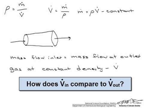
 let’s look at it together:

Turbine Flow Meter Advantages and Disadvantages

Advantages:

  1. High precision. Generally up to ±1%R, ±0.5%R.
  2. Output pulse frequency signal. It is suitable for total measurement and connection with computer. No zero drift, strong anti-interference ability.
  3. The structure is compact and lightweight. Easy installation and maintenance. Great flow capacity.
  4. Good repeatability, short-term repeatability can reach 0.05~0.2%. It is because of good repeatability. Frequent calibration or in-line calibration results in extremely high accuracy.
  5. There are many types of special sensors. It can be specially designed according to user needs. Such as: low temperature type, bidirectional, downhole type, special type for sand mixing, etc.
  6. The pressure compensation can be performed under the stable pressure state of the measured gas.
  7. The range is wide, the medium and large diameters can reach 1:20, and the small diameters are 1:10.

Disadvantages:

  1. Regular calibration is required. There is no way to maintain accuracy for long periods of time. Cannot work continuously for a long time.
  2. Higher requirements for the cleanliness of the medium. But filters can be installed.
  3. The flowmeter is greatly affected by the flow velocity distribution of the incoming flow (a flow regulator can be installed).
  4. It is not suitable for places where the flow rate changes rapidly.
  5. Not suitable for testing corrosive media.

Turbine Type Flow Meter Installation Guidelines

In order to ensure the accurate measurement of the turbine flowmeter, the installation location and method must be selected correctly.

  1. Requirements for straight pipe sections:
    • The flowmeter must be installed horizontally on the pipeline (the inclination of the pipeline is within 50), the axis of the flowmeter should be concentric with the axis of the pipeline during installation, and the flow direction should be consistent.
    • The length of the upstream pipeline of the flowmeter should have an equal diameter straight pipe section of not less than 2D. If the installation site is allowed, it is recommended that the upstream straight pipe section is 20D and the downstream is 5D.
  1. Requirements for piping:
    The inner diameter of the upstream and downstream piping at the installation point of the flowmeter is the same as the inner diameter of the flowmeter.
  2. Requirements for bypass pipes:
    In order to ensure that the normal use of the medium is not affected during the maintenance of the flowmeter, a cut-off valve (stop valve) should be installed on the front and rear pipelines of the flowmeter, and a bypass pipeline should be set at the same time. The flow control valve should be installed downstream of the flowmeter. When the flowmeter is used, the shut-off valve installed upstream must be fully opened to avoid unstable flow of the fluid in the upstream part.
  3. Requirements for the external environment:
    The turbine flowmeter is best installed indoors. When it must be installed outdoors, sun protection, rain protection and lightning protection measures must be adopted to avoid affecting the service life.
  4. Requirements for impurities contained in the medium:
    In order to ensure the service life of the flowmeter, a filter should be installed before the straight pipe section of the flowmeter.
  5. Installation site:
    The flowmeter should be installed in a place that is easy to maintain and free from strong electromagnetic interference and heat radiation
  6. Requirements for installation and welding:
    The user can configure a pair of standard flanges to be welded on the front and rear pipes. Welding with flow meter is not allowed!
    Before installing the flowmeter, the welding slag and other dirt in the pipeline should be strictly removed. To ensure that the flowmeter is not damaged during use.

Frequently
Asked
Questions

If the flowmeter is divided into 5 categories. Then the five commonly used flowmeters are:

  1. Electromagnetic flowmeter
  2. Differential pressure flowmeter
  3. Turbine flowmeter
  4. Ultrasonic flowmeter
  5. Volumetric flowmeter (PD)

For liquids, it is generally ±0.25%R-±0.5%R,
High precision type can reach ±0.15%R;

And the medium is gas, generally ±1%R-±1.5%R;
The special type is ±0.5%R-±1%R.

Turbine flowmeter is the main type of velocity flowmeter. It uses a multi-blade rotor (turbine) to sense the average flow rate of the fluid, and derives the flow or total amount of the meter.

More abou: More Details About Turbine Flow Meter

For different working principle, We offer different types of flow meters, like:

  • Differential Pressure Flow Meters
  • Orifice Plate
  • Venturi Tube
  • Flow Nozzles
  • The Sonic Nozzle – Critical (Choked) Flow Nozzle
  • Calorimetric Flowmeter
  • Ultrasonic Doppler Flowmeter
  • Positive Displacement Flowmeter
  • Variable Area Flowmeter or Rotameter
  • Velocity Flowmeters
  • Pitot Tubes
  • Electromagnetic Flowmeter
  • Turbine Flowmeter
  • Vortex Flow Meter
  • Thermal Flowmeter
  • Coriolis Flowmeter
  • Mass Flowmeters
  • Open Channel Flowmeters

Turbine flowmeters are widely used in the following measurement objects:
Petroleum, organic liquids, inorganic liquids, liquefied gases, natural gas, natural gas and cryogenic fluids.

Transshipment and centralized transportation stations for liquefied petroleum gas, refined oil and light crude oil abroad. The first and second stations of large crude oil pipelines are widely used for trade settlement.

More Flow Measurement Solutions

  • Flow Pressure Transducers for Fluid Pipelines

    Flow Pressure Transducers are measurements of fluid pressure within a pipeline. When fluid flows through a pipe, pressure acts on the pipe wall. The medium in the pipeline can be…
  • Crude Oil Flow Meter

    Crude Oil Flow Meter refers to a type of flow meter that can accurately monitor and measure the flow of crude oil. Crude oil is an industrial raw material with…
  • Non Contact Flow Meters Measure Liquid Flow

    What is non contact flow meter? Non Contact Flow Meters refers to flow meters that can achieve flow measurement without contacting the fluid medium. No need to destroy the pipeline…
  • Mechanical Oil Flow Meters

    What is mechanical oil flow meter? Mechanical oil flow meter refers to a flowmeter that can detect the volume flow of oil inline. Most importantly, this type of flowmeter is…
  • Clamp on Water Flow Meter

    What is Clamp on Water Flow Meter? Clamp on Water Flow Meter is also known as the clamp-on ultrasonic flowmeter. Using an ultrasonic flowmeter to measure water flow rate is…
  • Kerosene Gasoline/ Kerosene Flow Meter

    A kerosene flow meter is a flow meter that can be used to measure the flow of kerosene. Kerosene is a common oil in industrial production. It is an organic…
  • Slurry Flow Meter

    Flow Meter for Slurry Application Slurry is a product of domestic sewage and industrial wastewater treatment. Slurry consists of solid impurities, a slurry of suspended substances. The main characteristic of…
  • Measuring Steam Flow and Steam Flow Meters

    Measuring Steam Flow Measuring Steam Flow is a difficult task. But again, it’s a very important thing. Steam flow measurement is difficult, the main reason is determined by the characteristics…

This article “Turbine Flow meter Vs Gear Flow meter”, Sino-Inst provides you. Please indicate the source!

Sino-Inst, Manufacturer for Turbine Flow meter & Gear Flowmeters, like gas turbine flow meter, liquid turbine flow meter, sanitary turbine flow meter, insertion turbine flow meter, steam turbine flow meter, and natural gas turbine flow meter.

Sino-Inst’s Turbine Flow meter & Gear Flow meter, made in China, Having good Quality, With better price. Our flow measurement instruments are widely used in China, India, Pakistan, the US, and other countries.

Inaccurate level measurement of liquid ammonia storage tank

The liquid level of the liquid ammonia storage tank is accurately measured, which can eliminate potential safety hazards.

Choosing a suitable monitoring instrument for liquid ammonia storage is a prerequisite for ensuring safe production. The main instruments in the liquid ammonia tank area include liquid level, temperature, pressure, toxic (flammable) gas alarms, etc. For tank farms where the system is rebuilt, and environments where wiring is difficult, wireless instrumentation solutions can be used.

This article analyzes the application problems of several common liquid ammonia storage tank level measuring instruments. So as to provide a basis for the selection of measuring instruments.

About Liquid Ammonia Storage Tank

Liquid ammonia is a common chemical raw material. To facilitate transportation and storage, gaseous ammonia is usually pressurized or cooled to obtain liquid ammonia. When liquid ammonia is dissolved in water, ammonium ion NH4+ and hydroxide ion OH- are formed, and the solution is alkaline. Liquid ammonia is mostly stored in pressure cylinders or steel tanks. Liquid ammonia is widely used in industry, is corrosive and easily volatile, so its chemical accident rate is very high.

Read more about: 7 Level Senors for Tank Level Measurement

Application Analysis of Common liquid Ammonia Storage Tank Level Measuring Instruments

External liquid level sensor

The external level gauge is an instrument that uses the sonar ranging principle and “micro-vibration analysis” technology to measure the level from the outside of the container. No need to make holes on the tank wall, no flanges, no fire, no tank cleaning. Do not touch the liquid and gas in the tank. It can realize online installation and maintenance. It is a completely non-contact isolated instrument.


HS-2000 External Mounted Ultrasonic Tank Level Sensor- (referred to as “external level gauge”). It adopts advanced signal processing technology and high-speed signal processing chip. It breaks through the influence of container wall thickness. Realizes the height of the liquid level in the closed container True non-contact measurement.

The ultrasonic liquid level sensor (probe) is installed directly under the outer wall (bottom) of the container under test. Calibrate the outer wall of the probe. There is no need to open holes for the container to be tested, easy to install, and does not affect production. It can accurately measure the level of various toxic substances, strong acids, strong alkalis and various pure liquids in high-pressure airtight containers. The HS-2000 External Mounted Ultrasonic Tank Level Sensor has no special requirements for the material of the liquid medium and the container. The explosion-proof design is adopted to meet the explosion-proof requirements.


The external liquid level sensor continuously and accurately measures the liquid level in the tank from outside the tank. No contact with the liquid and gas in the tank at all, realizing a true isolation measurement. Therefore, the characteristics are as follows:

  1. Isolated non-contact liquid level measurement technology is very safe.
  2. Installation and debugging, thereby reducing construction and maintenance costs.
  3. It is more reliable and durable. There are no mechanical moving parts in the measuring probe and host, and it is strictly sealed, isolated from the outside world, and will not be worn or corroded.
  4. Pass the “functional safety integrity” level certification.

Differential pressure transmitter

One end of the differential pressure transmitter is connected to the liquid phase, and the other end is connected to the gas phase. The liquid level of the liquid ammonia storage tank can be measured using the principle of hydrostatics.

In the process of applying this instrument and equipment, it is necessary to strictly control the installation height of the equipment.

Generally, it needs to be installed below the lower interface of the liquid level pressure interface of the container under test. And choose easy to maintain and observe. At the same time, it is also close to the pressure taking part.

Taking into account the low boiling point and easy vaporization of liquid ammonia, it is necessary to use a double flange differential pressure transmitter to ensure the stability of the measurement signal.

If this device is used, the installation of the device will only be limited by the length of the capillary tube.

Specifically, it is necessary to take corresponding protection and insulation measures, and ensure that the bending radius of the capillary is greater than 50mm. When using this measuring instrument, if the installation elevation changes, the output value of the device will be affected.


Differential pressure(DP) level transmitter is often used as a tank level transmitter. The DP transmitter is connected with a stainless steel flange by capillary. Flange installation. The pressure is sensed by a remote transmission device installed on container. The pressure is transmitted to the body of the transmitter through the capillary. The transmitter convert the pressure or differential pressure to 4 ~ 20mA. The DC signal is output. It can communicate for the setting and monitoring by cooperating with the HART communicator. Explosion proof available.


From the application effect point of view, the differential pressure transmitter has the characteristics of easy calibration and a wide range of popularization. At the same time, the price of this type of equipment is low, and it has a certain cost-effective advantage.

However, when installing the device, it is necessary to reserve mounting holes. At the same time, due to the close relationship between the equipment and the density change of the medium, the measurement operation will cause the material of the instrument diaphragm to be corroded by the corrosive medium. After a long time of operation, the equipment is prone to deformation of the capsule.

In the application process, if there is no indication, the indication is too large or too small and the indication remains unchanged. It is also necessary to check the power supply, safety barriers, circuit boards, diaphragm capillaries and pressure valves. And appropriately replace the equipment components and open the equipment pressure valve in time.

Magnetic flap level gauge

The application of the magnetic flap level gauge follows the law of float and the principle of magnetism, and needs to be connected to the tank through a flange.

During the measurement, the two-color cylindrical magnetic float inside the device will change under the influence of the magnetic field, and the float junction is the actual liquid level of the storage tank.

In the process of installing the equipment, it is necessary to avoid magnetic materials around the equipment, and determine the heating temperature according to the medium condition. In the case of large gas-liquid-phase opening connections, a flange needs to be installed in the middle of the level gauge.

In the process of equipment debugging, a magnetic steel corrector is needed to adjust the magnetic column to white, and then open the gas phase stop valve and the liquid phase stop valve successively, and observe the liquid level rise and fall.

The magnetic flap level gauge can measure the liquid level and interface of any medium, and the equipment itself has the characteristics of convenient and intuitive installation.

However, if there are too many impurities in the medium, the magnetic column will not flip and the measurement will fail.

At the same time, the application of this device is prone to the problem of magnetic column jamming, which will lead to the failure of remote transmission instructions. However, the price of this equipment is low, and installation holes need to be reserved during installation.

The magnetic flap level gauge is prone to problems such as no signal output from the transmitter, no change in the output signal and the range cannot be adjusted to the corresponding value during the application process. In the application process, the power supply voltage, cables, terminal pins and safety barriers need to be checked.

Cable guided wave radar liquid level sensor

The application of the cable guided wave radar level gauge follows the principle of travel time, and it is necessary to measure the distance from the reference point to the surface of the liquid ammonia by transmitting and receiving high-frequency pulse signals.

When installing the equipment, it is necessary to avoid the liquid ammonia inlet to prevent false reflections from the equipment.

When installing the sensor, it cannot be installed in the center of the tank, and the sensor must be kept away from the tank wall.

When installing the cable probe, the distance between the probe and the smooth metal wall should be greater than 50mm, the distance between the end of the probe and the bottom of the container should be greater than 0mm, and the diameter of the short tube should not be greater than 0mm. In addition, depending on the installation position, the offset of the cable probe may increase.


Guided wave radar is a measuring instrument based on the principle of time travel. The radar wave runs at the speed of light. The operating time can be converted into level signals by electronic components. The probe emits high-frequency pulses and propagates along the cable or rod probe. When the pulse meets the surface of the material, it is reflected back and received by the receiver in the instrument. And convert the distance signal into level signal. SIRD-701 Guided Wave Radar Level Sensor is suitable for liquid and Bulk Solids measurement, and complex process conditions.


The cable-type guided wave radar level gauge has the characteristics of direct contact with the medium and small measurement blind area, and the measurement accuracy is high.

However, this equipment is not suitable for measuring pressure vessels, and the price is relatively high. It is necessary to reserve mounting holes on the top of the equipment during installation.

From the point of view of application failures, the equipment may have failures such as incorrect DCS system configuration, cable probe failure, and unstable DCS display value.

In the application process, it is necessary to carry out on-site measurement before calibration, and it is not necessary to check whether the DCS configuration data is consistent with the actual measurement result in order to obtain the real data.

Before measurement, you need to clean the probe and increase the height of the empty tank appropriately to eliminate the effect of echo.

You may like:

Use Differential Pressure Transmitter to Measure Liquid Level

Differential Pressure Level transmitter for Continuous tank level measurement.

A liquid level measurement solution that prevents the measured medium from directly acting on the transmitter.itle

In the chemical production, the medium often encounters problems such as impurities, crystal particles or agglomeration. It is easy to block the connecting pipeline. At this time, a flange-type differential pressure transmitter is required.

Silicone oil is filled in the closed system composed of the bellows, capillary tube and measuring chamber as the pressure transmission medium. The measured medium does not enter the capillary tube and the transmitter to avoid blockage.

Differential Pressure Level transmitters are divided into single flange type and double flange type according to their structure.

Only a flange between the container and the transmitter is called a single flange differential pressure transmitter.

As for the closed container whose upper end is isolated from the atmosphere, the upper space and atmospheric pressure are mostly different. Two flanges must be used to guide the liquid and gas phase pressure to the differential pressure transmitter. This is the double flange differential pressure transmitter.

Read more What is a diaphragm seal?

Differential Pressure Level transmitter for open containers

Open tank level measurement means that the tank is open to the atmosphere. Any change in atmospheric pressure will affect the process fluid pressure in the tank. In this liquid level measurement application, the low pressure side of the transmitter can measure the atmospheric pressure. This eliminates the influence of atmospheric pressure on the tank liquid level. The high-pressure side of the transmitter is connected to the tank. Therefore, the actual liquid level in the tank can be measured.

A single flange is used to measure the liquid level of an open tank.

Differential pressure range calculation method: Need to measure the height of the liquid level (unit: m) × acceleration of gravity (9.8) × measured medium density (unit: g/cm3) differential pressure range (unit: KPa).

The selection must know the measurement medium, measuring range, medium temperature, the size and pressure rating of the process connection flange, and the flange standard.

Extended Reading: Differential Pressure (DP) Flow Meters Technology

Differential Pressure Level transmitter for closed containers

For airtight containers, the inside is isolated from the atmosphere. When the process fluid fills or empties the tank, the pressure in the tank may change from positive pressure to vacuum. This change in tank pressure will directly affect the measured liquid level unless it is compensated for. This can be done by connecting the low-side pipe of the differential pressure transmitter to the top of the tank. Therefore, when measuring the liquid level of a closed tank, a differential pressure transmitter must be used.

Double flanges are used to measure the liquid level of a closed tank.

The calculation method of the differential pressure range: the height of the liquid level to be measured (unit: m) × acceleration of gravity (9.8) × (the density of the measured medium-the density of the capillary filling liquid) (unit: g/cm3) = differential pressure range (unit: KPa).

The selection must know the measurement medium, measuring range, medium temperature, pressure, capillary length, the size and pressure rating of the process connection flange and the flange standard

If you need to measure river water level, open channel level, etc. The Ultrasonic Liquid Level Sensor can be used for non-contact continuous level monitoring.

Read more about: 7 Level Senors for Tank Level Measurement

Differential pressure level transmitter working principle

When using Differential pressure (DP) level transmitter to measure the liquid level as shown in the figure below.
The measured liquid density in the figure is ρ.
The working medium density in the capillary of the double flange differential pressure transmitter is ρ0.
The measuring range of the measured liquid level is H.
The center distance of the sampling tube of the measured liquid level is h.
It can be seen from the figure that the maximum measurement range of the liquid level △ P = P + —P- = H × ρ × g-h × ρ0 × g.

It can be seen from the formula that the dual-flange differential pressure transmitter should perform negative migration. The migration amount S is h × ρ0 × g. And the installation position of the double flange differential pressure transmitter has no effect on the migration amount and the measurement result.

Extended reading: Hydrostatic Level Measurement

The dual-flange differential pressure transmitter requires negative migration.

When the measured liquid level is 0, the pressure difference between the positive and negative measurement chambers of the remote differential pressure transmitter is the largest. The output current of the double flange differential pressure transmitter is 4mA.

As the measured liquid level rises, the pressure difference between the positive and negative measurement chambers of the transmitter gradually decreases.

When the measured liquid level rises to the highest Hmax. The pressure difference between the positive and negative measurement chambers of the transmitter is the smallest. The output current of the double flange differential pressure transmitter is 20mA.

Extended Reading: Procurement Guide for Ultrasonic liquid level sensors

You may like:

Sino-Inst offers overs 100 DP transmitters for liquid level, pressure, flow, temperature measurement. Differential pressure (dp) level transmitters suit to measeure water and other liquid level.

A wide variety of DP level transmitters are available to you. Such as SMT3151LT Differential pressure level transmitter.

You can also choose from liquid flow meter and pressure transmitters, not specified. We are differential pressure level transmitter suppliers, located in China. The top supplying country is China(Mainland), which supply 100% of DP transmiters respectively.